Invacare M61 Owners Manual - Page 54
Invacare M61 Manual
 |
View all Invacare M61 manuals
Add to My Manuals
Save this manual to your list of manuals |
Page 54 highlights
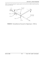
SECTION 9-FRONT RIGGINGS Inner Mounting Holes Seat Frame Mounting Bolts Spacer Locknuts Mounting Holes Telescoping Front Rigging Support 8 7 65 4 32 Not Used Hinge Pins FRONT RIGGING MODEL PHW93 PH904A and PHAL4A STANDARD POSITION 18 inches wide 20 inches wide Holes 4 and 5 Holes 4 and 5 Holes 3 and 4 Holes 3 and 4 1 INCH OUT 18 inches wide Holes 5 and 6 Holes 4 and 5 20 inches wide Holes 5 and 6 Holes 4 and 5 2 INCHES OUT 18 inches wide Holes 6 and 7 Holes 5 and 6 20 inches wide Holes 6 and 7 Holes 5 and 6 FIGURE 9.7 Adjusting/Replacing Telescoping Front Rigging Supports - Standard Seat ASBA Seat NOTE: For this procedure, refer to FIGURE 9.8 on page 55. 1. Remove the two mounting screws, spacers and locknuts that secure the telescoping front rigging support to the seat frame. 2. Perform one of the following: • Slide existing telescoping front rigging support to one of three depth positions. • Remove existing telescoping front rigging. 3. Secure telescoping front rigging at desired depth with existing two mounting screws, spacers, and locknuts. Securely tighten. Pronto® M51™and M61™with SureStep® 54 Part No 1125085
-
 1
1 -
2
-
3
-
4
-
5
-
6
-
7
-
8
-
9
-
10
-
11
-
12
-
13
-
14
-
15
-
16
-
17
-
18
-
19
-
20
-
21
-
22
-
23
-
24
-
25
-
26
-
27
-
28
-
29
-
30
-
31
-
32
-
33
-
34
-
35
-
36
-
37
-
38
-
39
-
40
-
41
-
42
-
43
-
44
-
45
-
46
-
47
-
48
-
 49
49 -
 50
50 -
 51
51 -
 52
52 -
 53
53 -
 54
54 -
 55
55 -
 56
56 -
 57
57 -
 58
58 -
 59
59 -
60
-
61
-
62
-
63
-
64
-
65
-
66
-
67
-
68
-
69
-
70
-
71
-
72
-
73
-
74
-
75
-
76
-
77
-
78
-
79
-
80
 |
 |
