Invacare M61 Owners Manual - Page 73
ELECTRONICS, Repositioning the Joystick
 |
View all Invacare M61 manuals
Add to My Manuals
Save this manual to your list of manuals |
Page 73 highlights
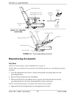
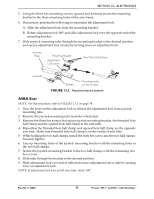
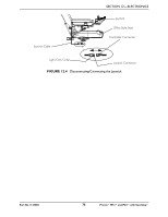
SECTION 12-ELECTRONICS 5. Using the three hex mounting screws, spacers and locknuts secure the mounting bracket to the three mounting holes of the arm frame. 6. If necessary, perform the following to reposition the adjustment lock: A. Slide the adjustment lock from the mounting bracket. B. Rotate adjustment lock 180° and slide adjustment lock over the opposite end of the mounting bracket. 7. Slide joystick mounting tube through the mounting bracket to the desired position and secure adjustment lock to tube by turning lever on adjustment lock. Armrest Plate Mounting Bracket Adjustment Lock Lever Hex Mounting Screws Locknuts Spacers Mounting Holes on Arm Frame FIGURE 12.2 Repositioning the Joystick ASBA Seat NOTE: For this procedure, refer to FIGURE 12.3 on page 74. 1. Turn the lever on the adjustment lock to release the adjustment lock from joystick mounting tube. 2. Remove the joystick mounting tube from the wheelchair. 3. Remove the three hex screws that secure joystick mounting bracket, the threaded hole half clamp and the opened hole half clamp to the arm tube. 4. Reposition the threaded hole half clamp and opened hole half clamp on the opposite arm tube. Make sure threaded hole half clamp is on the inside of arm tube. 5. While holding the two half clamps, install the front hex screw into the two half clamps. Securely tighten. 6. Line up mounting holes of the joystick mounting bracket with the mounting holes in the two half clamps. 7. Secure the joystick mounting bracket to the two half clamps with the remaining two hex screws. 8. Slide tube through the bracket to the desired position. 9. Slide adjustment lock over end of tube and secure adjustment lock to tube by turning lever on adjustment lock. NOTE: If adjustment lock does not fit over tube, rotate 180°. Part No 1125085 73 Pronto® M51™and M61™with SureStep®
-
 1
1 -
2
-
3
-
4
-
5
-
6
-
7
-
8
-
9
-
10
-
11
-
12
-
13
-
14
-
15
-
16
-
17
-
18
-
19
-
20
-
21
-
22
-
23
-
24
-
25
-
26
-
27
-
28
-
29
-
30
-
31
-
32
-
33
-
34
-
35
-
36
-
37
-
38
-
39
-
40
-
41
-
42
-
43
-
44
-
45
-
46
-
47
-
48
-
49
-
50
-
51
-
52
-
53
-
54
-
55
-
56
-
57
-
58
-
59
-
60
-
61
-
62
-
63
-
64
-
65
-
66
-
67
-
 68
68 -
 69
69 -
 70
70 -
 71
71 -
 72
72 -
 73
73 -
 74
74 -
 75
75 -
 76
76 -
 77
77 -
 78
78 -
79
-
80
 |
 |
