JVC GY-DV550E Instruction Manual - Page 10
Controls, Indicators And Connectors
 |
View all JVC GY-DV550E manuals
Add to My Manuals
Save this manual to your list of manuals |
Page 10 highlights
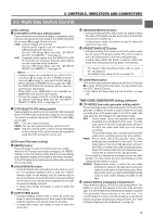
2. CONTROLS, INDICATORS AND CONNECTORS 2-1 Front Section q w VF !1 !0 PUSH e r t y OFF ZEBRA SKIN AUTO ON AREA WHITE ACCU FOCUS VTR AUDIO TAKE LEVEL CH-1 10 o i u 1 Viewfinder mount base, sliding securing ring Mount the viewfinder on the base and secure it using the sliding securing ring. See "Attaching the Viewfinder" on page 33. 2 [VF] Viewfinder connector (6-pin) Connect the cable from the viewfinder here. 3 [AUDIO IN FRONT] Audio input front connector (XLR 3-pin) Audio input terminal for connecting camera microphone or external audio devices. • Set AUDIO IN FRONT LINE/MIC switch 6 on page 23 according to the connecting device. • When recording audio from this terminal, set CH-1 AUDIO INPUT switch 7 or CH-2 AUDIO INPUT switch 8 to FRONT. See page 14. 1 3 2 Pin No. 1 2 3 Function GND HOT COLD CAUTION: The provided microphone is a phantom microphone. When using the provided microphone, set AUDIO IN FRONT LINE/MIC switch to MIC+48V ON. When using audio input device other than a phantom microphone, set AUDIO IN FRONT LINE/MIC switch to LINE or MIC before connecting the device. 4 [LENS] Lens control connector Connect 12-pin lens control cable from lens. 5 [ZEBRA] Switch When this switch is ON, a zebra pattern is superimposed on the viewfinder areas having video levels with a luminance level of 70% to 80%. This pattern can be used as a reference for manual adjustment of the lens iris. When CHARACTER MIX of the Camera SETUP Menu screen is set to ON, the zebra pattern will also appear in the MONITOR OUT connector video. Zebra patterns are also displayed during color bar display. * The zebra patterns are not generated for the Y/C OUT output. See "Zebra Pattern Display during Manual Adjustment" on page 87. • The default value is 70% - 80%. The luminance level can be changed with the ZEBRA setting in the VF DISPLAY Menu screen. See "ZEBRA" item on page 78. While this switch is pressed to the SKIN AREA side, the color tone areas specified with the SKIN DTL ADJUST item on the ADVANCED PROCESS MENU are indicated in the viewfinder. The switch returns to the OFF position when released. See "How to Use Skin Tone Detail" on page 91. • The Skin Tone Detail color tone areas are not indicated while the VTR playback picture is shown in the viewfinder. 6 [VTR] VTR trigger button (record start/stop button) Record start/stop can be effected with this button. (It is interlocked with the VTR trigger button on the lens section.) 7 [AUDIO LEVEL CH-1] CH-1 audio input level control Adjusts the audio input level of the CH1 audio signal. Normally, the camera is used with the control set to the maximum (10) position. • To use this control, set the VCR Setup Menu item No. 246 CH1 FRONT VR ENABLE to "ENABLE". Note: Even when the VCR Setup Menu item No. 246 is set to DISABLE, the recording level changes slightly when this control is turned. 8 [AUTO WHITE/ACCU FOCUS] switch AUTO WHITE: • First, position a white object to occupy 80% of the centre of the image. • Setting this switch to the upper position ("AUTO WHITE") will provide automatic adjustment for white balance. * It is not activated in preset, full auto shooting, full-time auto white balance and color bar modes. See "White Balance Adjustment" on page 47. ACCU FOCUS: • When this switch is set to "ACCU FOCUS" in the lower position, the lens iris will be forced to open for approximately ten seconds. 10
-
 1
1 -
2
-
3
-
4
-
 5
5 -
 6
6 -
 7
7 -
 8
8 -
 9
9 -
 10
10 -
 11
11 -
 12
12 -
 13
13 -
 14
14 -
 15
15 -
16
-
17
-
18
-
19
-
20
-
21
-
22
-
23
-
24
-
25
-
26
-
27
-
28
-
29
-
30
-
31
-
32
-
33
-
34
-
35
-
36
-
37
-
38
-
39
-
40
-
41
-
42
-
43
-
44
-
45
-
46
-
47
-
48
-
49
-
50
-
51
-
52
-
53
-
54
-
55
-
56
-
57
-
58
-
59
-
60
-
61
-
62
-
63
-
64
-
65
-
66
-
67
-
68
-
69
-
70
-
71
-
72
-
73
-
74
-
75
-
76
-
77
-
78
-
79
-
80
-
81
-
82
-
83
-
84
-
85
-
86
-
87
-
88
-
89
-
90
-
91
-
92
-
93
-
94
-
95
-
96
-
97
-
98
-
99
-
100
-
101
-
102
-
103
-
104
-
105
 |
 |
