JVC GY-DV550E Instruction Manual - Page 73
VCR Setup Menu Cont'd
 |
View all JVC GY-DV550E manuals
Add to My Manuals
Save this manual to your list of manuals |
Page 73 highlights
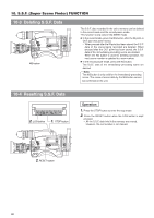
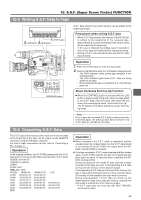
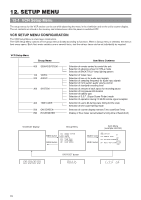
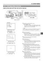
12-1 VCR Setup Menu (Cont'd) DISPLAYING AND SETTING VCR SETUP MENUS 12. SETUP MENU FILTER 1 3200k 2 5600k+1/8ND 3 5600k+1/64ND SHUTTER STATUS MENU ALARM MONITOR AUTO IRIS FULL AUTO BLACK BACK L NORMAL SPOT L STRETCH NORMAL COMPRESS LOLUX VTR GAIN OUTPUT WHT.BAL NG OPERATE ON OFF OPERATE/WARNING RESET MONITOR SELECT CH-1 MIX CH-2 LIGHT ON OFF COUNTER CTL TC UB CH-1 AUDIO CH-2 LEVEL CH-1 CH-2 AUTO MANUAL AUDIO SELECT CH-1 CH-2 FRONT REAR AUDIO INPUT MODE RM VTR INCOM MIC CARBON DYNAMIC INCOM MIC ON LEVEL OFF CALL RM OFF DC IN /BATT. POWER "MENU" indication CH-1 AUDIO LEVEL CH-2 CH-1 CH-2 AUTO MANUAL AUDIO SELECT CH-1 CH-2 FRONT REAR AUDIO INPUT SEE INSTRUCTION MANUAL LITHIUM BATT. VTR SELECT TC GENE. CONTINUE INT PARA PRST REC FREE EXT REGEN MENU GROUP ITEM SELECT DATA SET CAM AUX HOLD SHIFT ADVANCE PRESET VTR INPUT 2. 4. 3.5. 1. 6. Viewfinder 000 100 200 300 400 500 HM : SERVO / SYSTEM : V I DEO : AUD I O : SYSTEM : T I ME CODE : ON SCREEN : HOUR METER GROUP menu screen Counter display 2 4 4 : LOW CUT OF F 2 4 5 : SAMP L E RATE 48K 2 4 6 : CH1 FRONT VR ENAB L E 2 5 7 : AUD I O REF . S I GNA L L EV - 20dB Item menu screen DATA SET DATA SET display 1. Engaging the VCR Setup Menu mode. Press the MENU button. • The "MENU" indication in the display section starts blinking and the VCR Setup Menu appears in the viewfinder and on the counter display. Note: When a cable is connected to the REMOTE connector, the VTR Setup Menu is not displayed in the viewfinder. 2. Selecting the GROUP. Press the GROUP button. • Each time the GROUP button is pressed the selected GROUP number is shown blinking on the viewfinder screen. The counter display shows the selected group. 3. Open the Item menu of the selected GROUP. Press the SELECT button. 4. Selecting the Item. Press the ITEM button. • Each time the ITEM button is pressed the selected item number is shown blinking on the viewfinder screen. The counter display shows the selected item. 5. Changing the setting value of the item. Press the SELECT button and select the setting value. When multiple items should be set, repeat the operations of steps 4. and 5. To set menu items in other groups, press the MENU button. When the relevant group menu is displayed, perform the setting. When the GROUP button is pressed, the items of the higher order group menu are displayed. 6. Saving the setting value. Press the DATA SET button. • "DATA SET" appears in the viewfinder and on the counter display and the setting value is saved in the GY-DV550's memory. The display returns to the normal screen mode when data has been saved. If the MENU button is pressed without pressing the DATA SET button, the display returns to the normal screen mode without the setting value being changed. 73
-
 1
1 -
2
-
3
-
4
-
5
-
6
-
7
-
8
-
9
-
10
-
11
-
12
-
13
-
14
-
15
-
16
-
17
-
18
-
19
-
20
-
21
-
22
-
23
-
24
-
25
-
26
-
27
-
28
-
29
-
30
-
31
-
32
-
33
-
34
-
35
-
36
-
37
-
38
-
39
-
40
-
41
-
42
-
43
-
44
-
45
-
46
-
47
-
48
-
49
-
50
-
51
-
52
-
53
-
54
-
55
-
56
-
57
-
58
-
59
-
60
-
61
-
62
-
63
-
64
-
65
-
66
-
67
-
 68
68 -
 69
69 -
 70
70 -
 71
71 -
 72
72 -
 73
73 -
 74
74 -
 75
75 -
 76
76 -
 77
77 -
 78
78 -
79
-
80
-
81
-
82
-
83
-
84
-
85
-
86
-
87
-
88
-
89
-
90
-
91
-
92
-
93
-
94
-
95
-
96
-
97
-
98
-
99
-
100
-
101
-
102
-
103
-
104
-
105
 |
 |
