JVC GY-DV550E Instruction Manual - Page 23
Rear Cont'd
 |
View all JVC GY-DV550E manuals
Add to My Manuals
Save this manual to your list of manuals |
Page 23 highlights
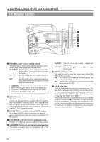
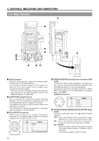
2. CONTROLS, INDICATORS AND CONNECTORS 2-6 Rear Section (Cont'd) 6 [AUDIO IN FRONT LINE/MIC] AUDIO IN FRONT select switch Selects the audio signal input to the AUDIO IN FRONT connector 3 on page 10. LINE : Set to this position when connected to audio equipment, etc. The reference input level is +4 dBs. MIC : Set to this position when the microphone is connected. The reference input level is -60 dBs. MIC +48V ON: Set to this position when a microphone requiring +48 V power supply (phantom microphone, etc.) is connected. This connector supplies +48 V DC current. Use this setting when using the provided microphone. CAUTION: When connecting a component that does not require +48 V power supply, make sure that the switch is not set to this position before the connection is made. 7 [INTERCOM] intercom input terminal (XLR 5-pin) Input terminal for the intercom headset. Connect the JVC Intercom KA-310 to this terminal. This terminal is enabled when the VTR/RM connector (26pin) on page 21 is connected to the camera control unit. (Enabled when the MODE switch 6 on page 20 is set to RM.) ! [BREAKER] The breaker trips when the power consumption exceeds the capacity. If the breaker trips, confirm that the power consumption does not exceed the wattage rating. Then press BREAKER before turning the power ON again to put the camera in the operating status. If the unit still does not work normally, please consult the person in charge of professional video equipment at your nearest JVC-authorized service agent. 8 [DC INPUT] connector (XLR 4-pin) Power input connector for 12 V DC. Connect with the AAP250 optional AC power adapter. When a cable is connected here, the power supply from the battery pack is interrupted and the source is switched to the power supplied through this connector. When supplying power to the unit from this connector or battery, set the POWER switch 1 on page 20 to DC IN/ BATT.. 1 4 23 No. Signal 1 GND 2 - 3 - 4 +12V 9 Battery holder Mount a Flat Shape type battery pack here. When supplying power to the unit from DC INPUT connector 8 or battery- set the POWER switch 1 on page 20 to DC IN/BATT. See "Attaching a Flat Shape Type Battery Pack" on page 38. 0 Battery holder lock release knob This knob is used to open the battery case cover. Press the knob to open the cover. 23
-
 1
1 -
2
-
3
-
4
-
5
-
6
-
7
-
8
-
9
-
10
-
11
-
12
-
13
-
14
-
15
-
16
-
17
-
 18
18 -
 19
19 -
 20
20 -
 21
21 -
 22
22 -
 23
23 -
 24
24 -
 25
25 -
 26
26 -
 27
27 -
 28
28 -
29
-
30
-
31
-
32
-
33
-
34
-
35
-
36
-
37
-
38
-
39
-
40
-
41
-
42
-
43
-
44
-
45
-
46
-
47
-
48
-
49
-
50
-
51
-
52
-
53
-
54
-
55
-
56
-
57
-
58
-
59
-
60
-
61
-
62
-
63
-
64
-
65
-
66
-
67
-
68
-
69
-
70
-
71
-
72
-
73
-
74
-
75
-
76
-
77
-
78
-
79
-
80
-
81
-
82
-
83
-
84
-
85
-
86
-
87
-
88
-
89
-
90
-
91
-
92
-
93
-
94
-
95
-
96
-
97
-
98
-
99
-
100
-
101
-
102
-
103
-
104
-
105
 |
 |
