JVC GY-DV550E Instruction Manual - Page 18
Left Side - gy dv550 camcorder
 |
View all JVC GY-DV550E manuals
Add to My Manuals
Save this manual to your list of manuals |
Page 18 highlights
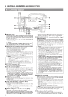
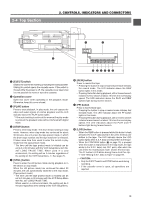
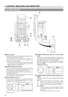
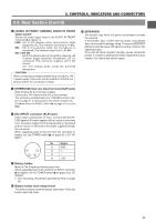
2. CONTROLS, INDICATORS AND CONNECTORS 2-3 Left Side Section PUSH q w e VTR/RM DV CAMCORDER GY-DV550 PROMPTER OUTPUT Y/C OUT MONITOR OUT LINE OUT CH-1 CH-2 TC IN TC OUT REMOTE GENLOCK/AUX IN VIDEO OUT AUDIO IN FRONT LENS !0 o i u 1 Cassette cover rty Pressing the EJECT switch on top of the section opens this cover so that a videocassette can be inserted or removed from the unit. The cover can be locked automatically by pushing and closing it. • If the cassette cover is not closed, the GY-DV550 will remain inoperative. Memo: To prevent penetration of foreign objects into the unit, do not leave the unit with the cassette cover open. 2 [MONITOR OUT] monitor output connector (BNC) Connector for composite video signal output. The following video signals are outputted. • E-E video or playback video of VCR • Screen mixed with characters. • External video signal (When VTR INPUT switch is set to AUX) Select whether to output the E-E video/playback video of VCR or character-mixed screen by CHARACTER MIX of the Camera Setup screen. See page 83 Memo: • Select whether to output signals that include setup in the E-E video in SETUP of the Camera Setup screen. See page 83 * Setup is not included during E-E of IEEE1394. • VITC time code is not outputted from this connector. 3 [Y/C OUT] connector (4P) Separate YC video signal output connector. 4 [TC IN] connector (BNC) Input connector for the SMPTE-standard LTC signal. The built-in time code generator can be slave-locked with the input time codes. If the user's bits should also be slave-locked, set the VCR Setup Menu item No. 403 U-BIT SLAVE to "TC&UB". * When the TC GENE switch (& on page 15) is set to REC or REGEN, or the VCR Setup Menu item No. 398 SSF MODE is set to "CUE MODE" or "MARK MODE", slave-locking will not take place. For the slave lock of time code, see page 64. 5 TC OUT connector (BNC) Output connector for the LTC signal from the built-in time code generator. The time code recorded on the tape is not output in play mode. 6 [LINE OUT CH-1/CH-2] connector (RCA) Output connector for audio signals. • Outputs the input audio signal in the record and stop modes. • Outputs the playback audio signal in the playback mode. • Alarm sound is not output. 7 [VIDEO OUT] Video output connector (BNC) Connector for composite video signal output. Camera images are constantly outputted as through images. Camera images are outputted even during external video signal input (when VTR INPUT switch 9 on page 15 is set to AUX). 18 • Whether to output signals with setup can be selected in SETUP of the Camera Setup screen. See page 83 8 [GENLOCK/AUX IN] Generationlock/Aux signal input connector Synchronous signals (black burst signals) are inputted when the GY-DV550's camera image is synchronized with an external component. Composite video signals are inputted when recording video signals from an external device with this unit. Which video signals to input can be selected using the VTR INPUT switch on page 15. Memo: • Video signals from this connector are not outputted to the VTR/RM multi-pin connector 8 on page 21. • When the camera remote control unit is connected with setting the MODE switch 6 on page 20 to RM, this connector will be used for synchronous signal input regardless of the VTR INPUT switch setting. • The camera cannot be synchronized with a VCR playback signal. • When the power is switched ON while an external sync signal is input, the screen moves in a vertical direction for a few seconds. this is not a malfunction. • If the external sync signal is disrupted during recording, the "SYnc inh" (SYNC INHIBIT) indicator is displayed on the counter display and recording stops. • If the external sync signal is disrupted during playback, playback of the disturbed video image continues. Start playback again after synchronization is obtained and the signal is stabilized. • The screen will distort when inputting sync signals to both the main unit and camera remote control unit. • This external video signal input (AUX IN) connector is an auxiliary connector. The bandwidth of Y signals will be 6.75 MHz (8 bit) regardless of the inputted signal bandwidth. 9 [REMOTE] connector A part of the unit's functions can be controlled externally. For connecting the local remote control unit (RM-LP55/RMLP-57), nonlinear editing device, etc. • When connecting the local remote control unit, Set VTR Setup menu No. 050 REMOTE SELECT to LOCAL or IEEE1394. • When connecting a nonlinear editing device, set to IEEE1394+RS232C. For details, please consult your JVC dealer. Note: If you make an error in the setting, disconnect the connector cable before performing setting again. 0 Microphone attachment holes For attaching the microphone holder KA-A50 (optional). See "Attaching the Microphone (optional)" on page 34.
-
 1
1 -
2
-
3
-
4
-
5
-
6
-
7
-
8
-
9
-
10
-
11
-
12
-
 13
13 -
 14
14 -
 15
15 -
 16
16 -
 17
17 -
 18
18 -
 19
19 -
 20
20 -
 21
21 -
 22
22 -
 23
23 -
24
-
25
-
26
-
27
-
28
-
29
-
30
-
31
-
32
-
33
-
34
-
35
-
36
-
37
-
38
-
39
-
40
-
41
-
42
-
43
-
44
-
45
-
46
-
47
-
48
-
49
-
50
-
51
-
52
-
53
-
54
-
55
-
56
-
57
-
58
-
59
-
60
-
61
-
62
-
63
-
64
-
65
-
66
-
67
-
68
-
69
-
70
-
71
-
72
-
73
-
74
-
75
-
76
-
77
-
78
-
79
-
80
-
81
-
82
-
83
-
84
-
85
-
86
-
87
-
88
-
89
-
90
-
91
-
92
-
93
-
94
-
95
-
96
-
97
-
98
-
99
-
100
-
101
-
102
-
103
-
104
-
105
 |
 |
