JVC GY-DV550E Instruction Manual - Page 29
Status 1
 |
View all JVC GY-DV550E manuals
Add to My Manuals
Save this manual to your list of manuals |
Page 29 highlights
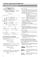
2. CONTROLS, INDICATORS AND CONNECTORS 2-10 Indications in Viewfinder (Cont'd) ● Status 1 In addition to the information on the Status 0 screen, this screen displays audio indicators and information on remaining tape, voltage and lens F-number (or FILTER POSITION). Display position Display 8 (Example) CH1 CH2 9 STBY SAVE STOP REC FF REW EJECT 0 (Example) < 60 (Example) 12: 34: 56: 20 A (Example) 12.4V B F-number: OPEN, F2, F2.8, F4, F5.6, F8, F11, F16, CLOSE FILTER: FIL1, FIL2, FIL3 C (Example) M: 099 D EXT, INT, PARA E REC2 Function Shows the input level of the audio input channel. Display ON/OFF can be selected using the VF DISPLAY menu screen. See "AUDIO DISPLAY" on page 78. VCR in standby mode VCR in save mode VCR in stop mode VCR in record mode Note: When the RS-232C cable is connected, the VCR VCR in fast-forward mode VCR in rewind mode VCR in eject mode operation mode may not be displayed correctly. Remaining tape indication (displayed in 1-minute steps) When the tape is used for a long time, the remaining tape may not be indicated accurately. At the beginning of the tape, in particular, the indication may show smaller value than the actual one. Time code display Time code display is available when the "REC TIME" item on the VF DISPLAY menu screen is set to TIME CODE. See "REC TIME" on page 78. Voltage indication (displayed in 0.1 V steps) The indicator flashes when the battery is low. The indicator will not appear when the camera remote control unit is connected. The F-number of the connected lens or the filter position of the unit is displayed. Whether to display the F-number or filter position, or no display is selected in F. NO/FILTER of the VF DISPLAY screen. • The F-number may not be displayed depending on the lens type or when the lens is removed. See page 78 Not displayed during external video signal input or IEEE1394 input. In the Super Scene Finder (S.S.F.) mode, the number of memorized scenes is shown. M : In MARK mode C : In CUE mode Number: Number of memorized scenes Displays whether the main unit is used for recording or the external VCR connected to the VTR/RM multi-pin connector. The displays will differ depending on the VTR SELECT switch setting. INT is constantly displayed during external video input or IEEE1394 input. INT is constantly displayed when the VTR/RM switch is set to RM. The display will light during external VCR recording. The display flashes when there is a warning on the external VCR. The display will not appear when the VTR/RM switch is set to RM. ● Status 2 ... Not displayed during external video signal input or IEEE1394 input. This screen displays the camera setup statuses. Event display is not available while this screen is displayed. Indication Indication Contents SCENE FILE A, B, OFF WHITE BAL A, B, PRESET, FAW, MANUAL (When remote control unit w/manual balance is connected.) FILTER 3.2K, 5.6K+1/8ND, 5.6K+1/64ND SHUTTER OFF, 1/100, 1/250, 1/500, 1/1000, 1/2000, 1/60.1 to 1/2084.6 (in VARIABLE mode), EEI (in ALC mode) GAIN -3dB, 0dB, 3dB, 6dB, 9dB, 12dB, 18dB, LOLUX, ALC IRIS LEVEL NORMAL, BACK L, SPOT L FULL AUTO ON, OFF REC TIME Remaining tape time or time code. 29
-
 1
1 -
2
-
3
-
4
-
5
-
6
-
7
-
8
-
9
-
10
-
11
-
12
-
13
-
14
-
15
-
16
-
17
-
18
-
19
-
20
-
21
-
22
-
23
-
 24
24 -
 25
25 -
 26
26 -
 27
27 -
 28
28 -
 29
29 -
 30
30 -
 31
31 -
 32
32 -
 33
33 -
 34
34 -
35
-
36
-
37
-
38
-
39
-
40
-
41
-
42
-
43
-
44
-
45
-
46
-
47
-
48
-
49
-
50
-
51
-
52
-
53
-
54
-
55
-
56
-
57
-
58
-
59
-
60
-
61
-
62
-
63
-
64
-
65
-
66
-
67
-
68
-
69
-
70
-
71
-
72
-
73
-
74
-
75
-
76
-
77
-
78
-
79
-
80
-
81
-
82
-
83
-
84
-
85
-
86
-
87
-
88
-
89
-
90
-
91
-
92
-
93
-
94
-
95
-
96
-
97
-
98
-
99
-
100
-
101
-
102
-
103
-
104
-
105
 |
 |
