JVC GY-DV550E Instruction Manual - Page 21
Adapter continued
 |
View all JVC GY-DV550E manuals
Add to My Manuals
Save this manual to your list of manuals |
Page 21 highlights
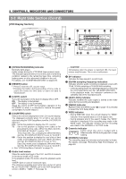
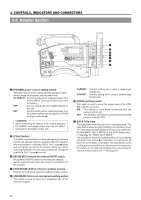
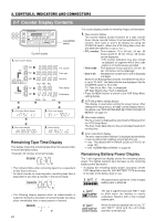
2. CONTROLS, INDICATORS AND CONNECTORS 2-5 Adapter Section (continued) PUSH 7 8 9 VTR/RM DV CAMCORDER GY-DV550 PROMPTER OUTPUT Y/C OUT MONITOR OUT LINE OUT CH-1 CH-2 TC IN TC OUT REMOTE GENLOCK/AUX IN VIDEO OUT AUDIO IN FRONT LENS 8 [VTR/RM] VTR/RM multi-pin connector (26P) This connector is used to connect an external VCR or camera control unit. Camera image signals are outputted from this connector. Set MODE switch 6 according to the connecting device. Memo: • Camera images of this unit are recorded on the external VCR. Compost video signals from GENLOCK/ AUX IN connector 8 on page 18 are not recorded. • When recording on an external VCR, set the VTR INPUT switch 9 on page 15 to CAM and set the VTR SELECT switch = to PARA or EXT. • Only CH1 audio can be outputted for audio signals. 9 [PROMPTER OUTPUT] prompter output connector Return video signals of the external VCR or signals inputted to the AUX input connector of the camera remote control unit are outputted through VTR/RM multi-pin connector 8. 21
-
 1
1 -
2
-
3
-
4
-
5
-
6
-
7
-
8
-
9
-
10
-
11
-
12
-
13
-
14
-
15
-
 16
16 -
 17
17 -
 18
18 -
 19
19 -
 20
20 -
 21
21 -
 22
22 -
 23
23 -
 24
24 -
 25
25 -
 26
26 -
27
-
28
-
29
-
30
-
31
-
32
-
33
-
34
-
35
-
36
-
37
-
38
-
39
-
40
-
41
-
42
-
43
-
44
-
45
-
46
-
47
-
48
-
49
-
50
-
51
-
52
-
53
-
54
-
55
-
56
-
57
-
58
-
59
-
60
-
61
-
62
-
63
-
64
-
65
-
66
-
67
-
68
-
69
-
70
-
71
-
72
-
73
-
74
-
75
-
76
-
77
-
78
-
79
-
80
-
81
-
82
-
83
-
84
-
85
-
86
-
87
-
88
-
89
-
90
-
91
-
92
-
93
-
94
-
95
-
96
-
97
-
98
-
99
-
100
-
101
-
102
-
103
-
104
-
105
 |
 |
