JVC GY-DV550E Instruction Manual - Page 20
Adapter
 |
View all JVC GY-DV550E manuals
Add to My Manuals
Save this manual to your list of manuals |
Page 20 highlights
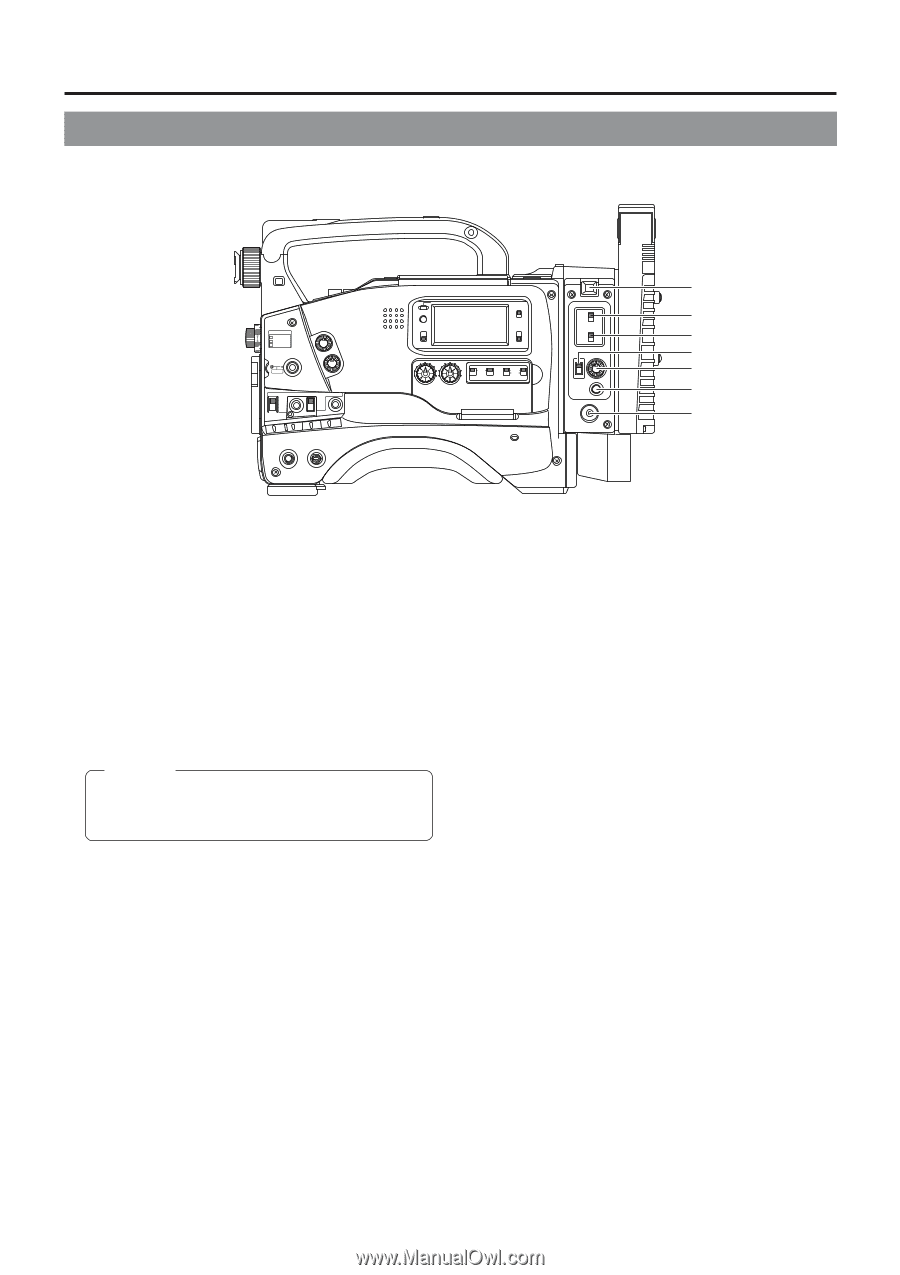
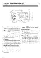
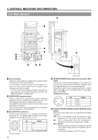
2. CONTROLS, INDICATORS AND CONNECTORS 2-5 Adapter Section FILTER 1 3200k 2 5600k+1/8ND 3 5600k+1/64ND SHUTTER STATUS MENU ALARM MONITOR AUTO IRIS FULL AUTO BLACK BACK L NORMAL SPOT L STRETCH NORMAL COMPRESS LOLUX VTR GAIN OUTPUT WHT.BAL NG OPERATE ON OFF OPERATE/WARNING RESET MONITOR SELECT CH-1 MIX CH-2 LIGHT ON OFF COUNTER CTL TC UB CH-1 AUDIO CH-2 LEVEL CH-1 CH-2 AUTO MANUAL AUDIO SELECT CH-1 CH-2 FRONT REAR AUDIO INPUT MODE RM VTR INCOM MIC CARBON DYNAMIC INCOM MIC ON LEVEL OFF CALL RM OFF DC IN /BATT. POWER u y t e r w q 1 [POWER] power source setting switch The power source to this unit is selected using this switch. When turning on the power, set this switch first. DC IN/BATT : Use this setting when supplying power from the DC INPUT connector of this unit or from the battery. OFF : Use this setting when not supplying power to this unit. RM : Use this setting when supplying power from the camera control unit through the VTR/RM multi-pin connector 8. CAUTION: When connecting an external VCR, set this switch to DC IN/BATT and supply power from the DC INPUT connector or the battery of this unit. 2 [CALL] button This button is pressed when sending call signals to a camera control unit operator without using the intercom headset. When this button is held down, BACK TALLY lamp 7 blinks and call signals are sent to the camera control unit. When releasing this button, the unit stops sending the call signals and BACK TALLY lamp 7 turns off. 3 [INCOM MIC] intercom microphone ON/OFF switch Microphone ON/OFF switch for the intercom headset. Set the switch to OFF when not using the microphone of the headset. 4 [INTERCOM LEVEL] intercom receiver volume Knob for controlling the intercom headset receiver volume. 5 [INCOM MIC] intercom microphone setting switch This switch is used to select the microphone type of the intercom headset. CARBON : Use this setting when using a carbon-type microphone. DYNAMIC : Use this setting when using a dynamic-type microphone. 6 [MODE] setting switch This switch is used to select the usage mode of the VTR/ RM multi-pin connector. RM : This setting is used when connecting with the camera control unit. VTR : This setting is used when connecting and recording using an external VCR 7 BACK Tally lamp This lamp lights when the unit is in the recording mode. The lamp flashes when the unit is shifting to the recording mode. The lamp status and the lighting method can be selected in No.082 BACK TALLY MODE of the VCR Setup menu. See page 74, "BACK TALLY MODE" The lamp blinks when the camera control unit is connected and while CALL button 2 is held down. The lamp turns off when the CALL button is released. The lamp flashes when a call signal is received from a camera control unit operator. For details on the tally lamp display when connecting the camera remote control unit, See page 95. 20
-
 1
1 -
2
-
3
-
4
-
5
-
6
-
7
-
8
-
9
-
10
-
11
-
12
-
13
-
14
-
 15
15 -
 16
16 -
 17
17 -
 18
18 -
 19
19 -
 20
20 -
 21
21 -
 22
22 -
 23
23 -
 24
24 -
 25
25 -
26
-
27
-
28
-
29
-
30
-
31
-
32
-
33
-
34
-
35
-
36
-
37
-
38
-
39
-
40
-
41
-
42
-
43
-
44
-
45
-
46
-
47
-
48
-
49
-
50
-
51
-
52
-
53
-
54
-
55
-
56
-
57
-
58
-
59
-
60
-
61
-
62
-
63
-
64
-
65
-
66
-
67
-
68
-
69
-
70
-
71
-
72
-
73
-
74
-
75
-
76
-
77
-
78
-
79
-
80
-
81
-
82
-
83
-
84
-
85
-
86
-
87
-
88
-
89
-
90
-
91
-
92
-
93
-
94
-
95
-
96
-
97
-
98
-
99
-
100
-
101
-
102
-
103
-
104
-
105
 |
 |