JVC GY-DV550E Instruction Manual - Page 16
VCR Display
 |
View all JVC GY-DV550E manuals
Add to My Manuals
Save this manual to your list of manuals |
Page 16 highlights
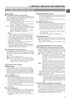
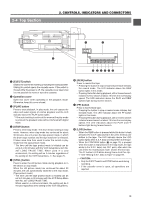
2. CONTROLS, INDICATORS AND CONNECTORS 2-2 Right Side Section (Cont'd) [VCR Display Section] wq FILTER 1 3200k 2 5600k+1/8ND 3 5600k+1/64ND SHUTTER STATUS MENU ALARM MONITOR AUTO IRIS FULL AUTO BLACK BACK L NORMAL SPOT L STRETCH NORMAL COMPRESS LOLUX VTR GAIN OUTPUT WHT.BAL NG OPERATE ON OFF OPERATE/WARNING RESET MONITOR SELECT CH-1 MIX CH-2 LIGHT ON OFF COUNTER CTL TC UB CH-1 AUDIO CH-2 LEVEL CH-1 CH-2 AUTO MANUAL AUDIO SELECT CH-1 CH-2 FRONT REAR AUDIO INPUT MODE RM VTR INCOM MIC CARBON DYNAMIC INCOM MIC ON LEVEL OFF CALL RM OFF DC IN /BATT. POWER u yt !7 !6 CH 1 OVER AUTO OFF DEW 40 30 20 10 0 dB e CH 2 OVER SERVO RF L i 32k 48k SLAVE PB NDF HOLD i AUD LOCK SP r o MENU WIDE H M S F REMAIN REV FWD E BATT F H M !0 !1 !2 !3 !4 !5 1 [OPERATE/WARNING] indicator Normally lights green. Lights orange during the VTR SAVE (tape protect) mode. This indicator lights or blinks in red in the case of a warning condition related to the remaining tape time, remaining battery power or other abnormal condition in the unit. For details, see "ALARM INDICATIONS" on pages 96. 2 [RESET] button • Press to reset the CTL counter value. * Pressing the button during presetting of time code or user's bit resets the time code or user's bit data to "00:00:00:00". 3 [LIGHT] switch Turns the illumination of the back-lit display ON or OFF. ON : The display is illuminated. OFF : The display is not illuminated. (Keep this switch at OFF during battery operation of the GY-DV550 or when it is required to reduce the power consumption for some reason.) 4 [COUNTER] switch Selects the contents displayed on the LCD counter display. The displayed contents when TC or UB is set can be selected using the VCR Setup Menu item No. 516 DISPLAY SELECT. CTL : Set to this position to display the CTL counter. TC : Set to this position to display time codes or for presetting the time code. (When the Menu item No. 516 DISPLAY SELECT is set to "TC") Time (Hour, Min., Sec.) is displayed. (When the Menu item No. 516 DISPLAY SELECT is set to "CLOCK") UB : Set to this position to display the user's bits of time codes or presetting the user's bit. (When the Menu item No. 516 DISPLAY SELECT is set to "TC") Date (Day, month, year) is displayed. (When the Menu item No. 516 DISPLAY SELECT is set to "CLOCK") See "VCR Setup Menu Contents" on page 75. 5 Audio level meters Show the audio input level of the CH-1 and CH-2 channels in the record mode or EE mode. In the playback mode, the meters show the playback audio level. "OVER" lights in case of excessive input. The reference recording level to the tape can be set using No. 257 AUDIO REF. SIGNAL LEV in the VCR Setup Menu screen (-20dB or -12dB). See page 74 CAUTION: Immediately after the power is switched ON, the level meters may fluctuate. This is not a malfunction. 6 SP indicator Indicates the tape speed in record mode. 7 32k/48k sampling frequency indication Indicates whether audio recording or playback occurs with 12-bit, 32 kHz sampling or 16-bit 48 kHz sampling. • In the recording mode, the sampling frequency is set using the VCR Setup Menu item No. 245 SAMPLING RATE. In the playback mode, the indication conforms to the sampling rate of the recorded sound. 8 [AUD LOCK] indicator Indicates whether the audio signal is locked to the video signal during recording and playback. 9 [MENU] indicator Appears when the MENU button 1 on page 15 is pressed to select the VCR Setup Menu. 0 WIDE indicator • During IEEE1394 input, the unit will display the "WIDE" indicator if the inputted data is of 16:9 aspect ratio. • During playback and in the search modes, the "WIDE" indicator is displayed if the recording was made in the WIDE mode. The indicator remains off if the recording was made in the NORMAL or LETTER mode. ! Cassette indicator Lights when the unit is loaded with a videocassette. Blinks during ejection or tape loading. @ [REMAIN] indicator The remaining tape time (minutes and seconds) is shown. For details, see page "Remaining Tape Time Display" on page 24. 16
-
 1
1 -
2
-
3
-
4
-
5
-
6
-
7
-
8
-
9
-
10
-
 11
11 -
 12
12 -
 13
13 -
 14
14 -
 15
15 -
 16
16 -
 17
17 -
 18
18 -
 19
19 -
 20
20 -
 21
21 -
22
-
23
-
24
-
25
-
26
-
27
-
28
-
29
-
30
-
31
-
32
-
33
-
34
-
35
-
36
-
37
-
38
-
39
-
40
-
41
-
42
-
43
-
44
-
45
-
46
-
47
-
48
-
49
-
50
-
51
-
52
-
53
-
54
-
55
-
56
-
57
-
58
-
59
-
60
-
61
-
62
-
63
-
64
-
65
-
66
-
67
-
68
-
69
-
70
-
71
-
72
-
73
-
74
-
75
-
76
-
77
-
78
-
79
-
80
-
81
-
82
-
83
-
84
-
85
-
86
-
87
-
88
-
89
-
90
-
91
-
92
-
93
-
94
-
95
-
96
-
97
-
98
-
99
-
100
-
101
-
102
-
103
-
104
-
105
 |
 |
