JVC GY-DV550E Instruction Manual - Page 71
Connecting a PC
 |
View all JVC GY-DV550E manuals
Add to My Manuals
Save this manual to your list of manuals |
Page 71 highlights
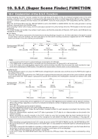
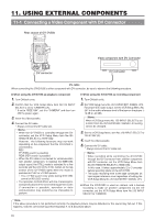
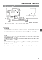
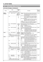
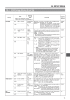
11-2 Connecting a PC PUSH 11. USING EXTERNAL COMPONENTS VTR/RM DV CAMCORDER GY-DV550 PROMPTER OUTPUT Y/C OUT MONITOR OUT LINE OUT CH-1 CH-2 TC IN TC OUT DV connector GENLOCK/AUX IN VIDEO OUT REMOTE AUDIO IN FRONT LENS TTL RS-232C REMOTE connector converter cable RS-232C RS-232C MONITOR OUT connector AUDIO IN (Optional VC-P893) AUDIO OUT VIDEO IN PC Non-linear editing controller DV connector Perform the following settings when connecting the unit to a Non-linear editing controller, etc. Connections Connect the GY-DV550's VTR REMOTE connector to the RS-232C connector on the PC or the non-linear editing controller using the TTL ⇔ RS-232C converter cable. Or connect the GY-DV550's DV connector and the DV connector of the non-linear editing controller using a DV cable. For compatible non-linear editing controller, consult with your JVC dealer. Settings • To remote control the PC or non-linear editing controller by means of RS-232C, set the VCR Setup Menu item No. 050 REMOTE SELECT to "IEEE1394+RS232C". See page 74. • To remote control the GY-DV550's VCR using the DV connector's IEEE1394 option, set the VCR Setup Menu item No. 050 REMOTE SELECT to "IEEE1394". See page 74. Note: • When a cable is connected to the REMOTE connector, the VTR Setup Menu is not displayed in the viewfinder. Make settings on the VTR Setup Menu while the cable is not connected. • When a cable is connected to the REMOTE connector, the VCR operation mode will not be displayed correctly on the Status 1 screen in the viewfinder. The S.S.F. data stored in the memory of the unit or at the beginning of the tape can be output through the REMOTE terminal. See page 69. 71
-
 1
1 -
2
-
3
-
4
-
5
-
6
-
7
-
8
-
9
-
10
-
11
-
12
-
13
-
14
-
15
-
16
-
17
-
18
-
19
-
20
-
21
-
22
-
23
-
24
-
25
-
26
-
27
-
28
-
29
-
30
-
31
-
32
-
33
-
34
-
35
-
36
-
37
-
38
-
39
-
40
-
41
-
42
-
43
-
44
-
45
-
46
-
47
-
48
-
49
-
50
-
51
-
52
-
53
-
54
-
55
-
56
-
57
-
58
-
59
-
60
-
61
-
62
-
63
-
64
-
65
-
 66
66 -
 67
67 -
 68
68 -
 69
69 -
 70
70 -
 71
71 -
 72
72 -
 73
73 -
 74
74 -
 75
75 -
 76
76 -
77
-
78
-
79
-
80
-
81
-
82
-
83
-
84
-
85
-
86
-
87
-
88
-
89
-
90
-
91
-
92
-
93
-
94
-
95
-
96
-
97
-
98
-
99
-
100
-
101
-
102
-
103
-
104
-
105
 |
 |
