JVC GY-DV550E Instruction Manual - Page 14
Right Side Cont'd
 |
View all JVC GY-DV550E manuals
Add to My Manuals
Save this manual to your list of manuals |
Page 14 highlights
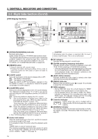
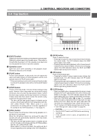
2. CONTROLS, INDICATORS AND CONNECTORS 2-2 Right Side Section (Cont'd) [VCR Setting Section] FILTER 1 3200k 2 5600k+1/8ND 3 5600k+1/64ND SHUTTER STATUS MENU ALARM MONITOR AUTO IRIS FULL AUTO BLACK BACK L NORMAL SPOT L STRETCH NORMAL COMPRESS LOLUX VTR GAIN OUTPUT WHT.BAL NG OPERATE ON OFF OPERATE/WARNING RESET MONITOR SELECT CH-1 MIX CH-2 LIGHT ON OFF COUNTER CTL TC UB CH-1 AUDIO CH-2 LEVEL CH-1 CH-2 AUTO MANUAL AUDIO SELECT CH-1 CH-2 FRONT REAR AUDIO INPUT MODE RM VTR INCOM MIC CARBON DYNAMIC INCOM MIC ON LEVEL OFF CALL RM OFF DC IN /BATT. POWER 5 67 8 CH-1 AUDIO LEVEL SEE INSTRUCTION MANUAL LITHIUM BATT. CH-2 CH-1 CH-2 AUTO MANUAL AUDIO SELECT CH-1 CH-2 FRONT REAR AUDIO INPUT VTR SELECT TC GENE. CONTINUE INT PARA PRST REC FREE EXT REGEN MENU GROUP CAM AUX HOLD ITEM SELECT DATA SET SHIFT ADVANCE PRESET VTR INPUT H0 9 B C D E FA G 1 23 [Audio setting] 1 Monitoring loudspeaker • Enables EE monitoring of the input audio signal during recording, in the record-pause mode or in the stop mode. Outputs the playback sound in the playback mode. The sound to be output can be selected using the MONITOR SELECT switch 4. • The loudspeaker volume can be adjusted with the MONITOR volume control 2 on page 12. The audio from the loudspeaker is not output when an earphone is plugged into the EARPHONE jack 2 on page 22. The warning alarm tones are also output through this loudspeaker. See "ALARM INDICATIONS" on pages 96. 2 [CH1 AUDIO LEVEL] CH1 audio input level control Adjust the audio input level of the CH1 audio channel with this control. • To use this control, set the CH1 AUDIO SELECT switch 5 to "MANUAL". This control works regardless of the setting of the VCR Setup Menu item No. 246 CH1 FRONT VR ENABLE. To use this control, set the AUDIO LEVEL CH-1 audio input level control (7 on page 10) on the front section to the maximum (10) position, or set the VCR Setup Menu item No. 246 CH1 FRONT VR ENABLE to "DISABLE". 3 [CH2 AUDIO LEVEL] CH2 audio input level control Adjust the audio input level of the CH2 audio channel with this control. • This control is valid only when the CH2 AUDIO SELECT switch 6 is set to "MANUAL". 4 [MONITOR SELECT] audio monitor selector switch This switch is used to select the monitor sound output from the monitoring loudspeaker 1 or via the EARPHONE jack 2 on page 22. CH-1 : The CH1 channel audio is output. MIX : CH1 and CH2 channel audio are output mixed. CH-2 : The CH2 channel audio is output. CAUTION: Make sure to move switches all the way. Do not leave a switch stopped in a midway position. Noise will be generated and operation irregularities will occur. 14 5 [CH-1 AUDIO SELECT] selector switch This switch is used to select the method for adjusting the audio input level of the CH-1 audio channel. The reference audio input level to the tape can be set using No. 257 AUDIO REF. SIGNAL LEVEL in the VCR Setup Menu screen (-20dB or -12dB). See page 74 AUTO : The audio input level is held at the reference level even when sounds greater than the reference level are input. The audio input level does not increase when the input level is low. MANUAL : The audio input level can be adjusted with the CH-1 AUDIO LEVEL control 2 or the CH-1 AUDIO LEVEL control 7 on page 10. To use the AUDIO LEVEL CH-1 audio input level control on the front section, set the VCR Setup Menu item No. 246 CH1 FRONT VR ENABLE to "ENABLE". 6 [CH-2 AUDIO SELECT] selector switch This switch is used to select the method for adjusting the audio input level of the CH-2 audio channel. The reference audio input level to the tape can be set using No. 257 AUDIO REF. SIGNAL LEVEL in the VCR Setup Menu screen (-20dB or -12dB). See page 74 AUTO : The audio input level is held at the reference level even when sounds greater than the reference level are input. The audio input level does not increase when the input level is low. MANUAL : The audio input level can be adjusted with the CH-2 AUDIO LEVEL control 3. 7 [CH-1 AUDIO INPUT] selector switch This switch is used to select the input section of the CH1 audio channel. FRONT : The sound from the AUDIO IN FRONT connector on the front side section is input. REAR : The sound from the AUDIO IN REAR connector on the rear side section is input. 8 [CH-2 AUDIO INPUT] selector switch This switch is used to select the input section of the CH2 audio channel. FRONT : The sound from the AUDIO IN FRONT connector on the front side section is input. REAR : The sound from the AUDIO IN REAR connector on the rear side section is input.
-
 1
1 -
2
-
3
-
4
-
5
-
6
-
7
-
8
-
 9
9 -
 10
10 -
 11
11 -
 12
12 -
 13
13 -
 14
14 -
 15
15 -
 16
16 -
 17
17 -
 18
18 -
 19
19 -
20
-
21
-
22
-
23
-
24
-
25
-
26
-
27
-
28
-
29
-
30
-
31
-
32
-
33
-
34
-
35
-
36
-
37
-
38
-
39
-
40
-
41
-
42
-
43
-
44
-
45
-
46
-
47
-
48
-
49
-
50
-
51
-
52
-
53
-
54
-
55
-
56
-
57
-
58
-
59
-
60
-
61
-
62
-
63
-
64
-
65
-
66
-
67
-
68
-
69
-
70
-
71
-
72
-
73
-
74
-
75
-
76
-
77
-
78
-
79
-
80
-
81
-
82
-
83
-
84
-
85
-
86
-
87
-
88
-
89
-
90
-
91
-
92
-
93
-
94
-
95
-
96
-
97
-
98
-
99
-
100
-
101
-
102
-
103
-
104
-
105
 |
 |
