JVC V685U Instructions - Page 13
Name and Function of Parts, VN-V685U/VN-V686BU, Ceiling mount
 |
View all JVC V685U manuals
Add to My Manuals
Save this manual to your list of manuals |
Page 13 highlights
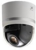
Name and Function of Parts VN-V685U/VN-V686BU Ⅵ Ceiling mount section Terminal H A G B C F D E A Fixing holes (x3) This hole is for mounting the ceiling clamping bracket to the ceiling or the ceiling recessed bracket (WB-S685: Sold separately). B [AC24VHINPUT] AC 24 V Input terminal This connects the camera to AC 24 V power. C [10BASE-T/100BASE-TX] LAN cable connection terminal This connects the unit to the network. It supports PoE (IEEE802.3af) and enables you to use this camera without having to connect to a power supply using a power cord. PoE: class0 (A Page 24) D Alarm input/Alarm output terminal This terminal is for alarm input/alarm output. (A Page 25) Pin number 1 2 3 4 5 6 7 8 Signal Name Input 1 Input 1 COM Input 2 Input 2 COM Output 1 Output 1 COM Output 2 Output 2 COM Reverse side J I E Fall prevention wire fixing bracket This attaches to the fall prevention wire J of the camera. F Wire clamp fixing hole This is used to bundle wires. (A Page 19) G Fall prevention wire mounting hole Mount wires from the ceiling slab or channel to this hole to prevent the camera from falling. H Power indicator The indicator lights up in green when AC 24 V power/ PoE power is turned on. I [Mac address] indication The MAC address is a unique physical address of the product. This address cannot be altered. J Camera connection terminal (female) This connects to the connection terminal (male) of the camera. 13
-
 1
1 -
2
-
3
-
4
-
5
-
6
-
7
-
 8
8 -
 9
9 -
 10
10 -
 11
11 -
 12
12 -
 13
13 -
 14
14 -
 15
15 -
 16
16 -
 17
17 -
 18
18 -
19
-
20
-
21
-
22
-
23
-
24
-
25
-
26
-
27
-
28
-
29
-
30
-
31
-
32
-
33
-
34
-
35
-
36
-
37
-
38
-
39
-
40
-
41
-
42
-
43
-
44
-
45
-
46
-
47
-
48
-
49
-
50
-
51
-
52
-
53
-
54
-
55
-
56
-
57
-
58
-
59
-
60
-
61
-
62
-
63
-
64
-
65
-
66
-
67
-
68
-
69
-
70
-
71
-
72
-
73
-
74
-
75
-
76
-
77
-
78
-
79
-
80
-
81
-
82
-
83
-
84
-
85
-
86
-
87
-
88
-
89
-
90
-
91
-
92
-
93
-
94
-
95
-
96
-
97
-
98
-
99
-
100
-
101
-
102
-
103
-
104
-
105
-
106
-
107
-
108
-
109
-
110
-
111
-
112
-
113
-
114
-
115
-
116
-
117
-
118
-
119
-
120
-
121
-
122
-
123
-
124
-
125
-
126
-
127
-
128
-
129
-
130
 |
 |
