JVC V685U Instructions - Page 26
Connection/Installation (VN-V686WPBU), Mounting the Camera, Setting Up the Wall
 |
View all JVC V685U manuals
Add to My Manuals
Save this manual to your list of manuals |
Page 26 highlights
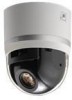
Connection/Installation (VN-V686WPBU) Mounting the Camera Setting Up the Wall 4 Pull the cables from the hole in the wall Pull the power cable, LAN cable and alarm signal cable from the wall. LAN Cable Be sure to put on protective glasses to protect your eyes from falling objects when mounting the camera. 1 Make holes in the wall Make holes (R 45 mm) for the connecting cables to pass through. Note: ● Check the strength of the wall. A less firm wall may cause the unit to fall. 2 Install the anchor bolts for mounting the camera Install 4 anchor bolts (M8 ן35 mm and above) to mount the camera. 3 Install the anchor bolt for mounting the fall prevention wire Install the anchor bolt (M8 ן35 mm and above) to mount the fall prevention wire 30 mm below the center of the upper two anchor bolts that are used to mount the camera. Power cable Alarm signal cable Setting Up the Camera 1 Remove the dome cover Loosen the screws (x4) and remove the dome cover from the camera. Dome Cover 152 126 63 45 3 Anchor bolt to mount the fall 1 prevention wire 60 20 12 30 176 213 2 Remove the cushioning material, lens cap and tape used during transporting When installing the heater at an unrequired location, turn off the switch of the heater. Tape Cushioning material 2 Anchor bolts to mount the camera Lens cap Heater power switch OFF 26
-
 1
1 -
2
-
3
-
4
-
5
-
6
-
7
-
8
-
9
-
10
-
11
-
12
-
13
-
14
-
15
-
16
-
17
-
18
-
19
-
20
-
 21
21 -
 22
22 -
 23
23 -
 24
24 -
 25
25 -
 26
26 -
 27
27 -
 28
28 -
 29
29 -
 30
30 -
 31
31 -
32
-
33
-
34
-
35
-
36
-
37
-
38
-
39
-
40
-
41
-
42
-
43
-
44
-
45
-
46
-
47
-
48
-
49
-
50
-
51
-
52
-
53
-
54
-
55
-
56
-
57
-
58
-
59
-
60
-
61
-
62
-
63
-
64
-
65
-
66
-
67
-
68
-
69
-
70
-
71
-
72
-
73
-
74
-
75
-
76
-
77
-
78
-
79
-
80
-
81
-
82
-
83
-
84
-
85
-
86
-
87
-
88
-
89
-
90
-
91
-
92
-
93
-
94
-
95
-
96
-
97
-
98
-
99
-
100
-
101
-
102
-
103
-
104
-
105
-
106
-
107
-
108
-
109
-
110
-
111
-
112
-
113
-
114
-
115
-
116
-
117
-
118
-
119
-
120
-
121
-
122
-
123
-
124
-
125
-
126
-
127
-
128
-
129
-
130
 |
 |
