Lenovo NetVista A22 Hardware Maintenance Manual (HMM) for NetVista 2254, 2256, - Page 74
Replacing a processor - Microtower Model, Power supply removal - Microtower Model
 |
View all Lenovo NetVista A22 manuals
Add to My Manuals
Save this manual to your list of manuals |
Page 74 highlights
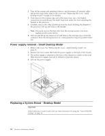
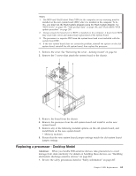
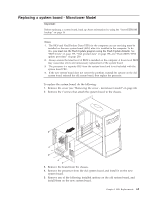
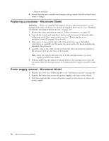
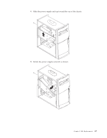
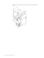
v Memory modules 6. Ensure that the new system board jumper settings match the old system board jumper settings. Replacing a processor - Microtower Model Attention: When you handle ESD-sensitive devices, take precautions to avoid damage from static electricity. For details on handling these devices, see "Handling electrostatic discharge-sensitive devices" on page 210. 1. Review the safety precautions listed in "Safety information" on page 207. 2. Turn off the system and peripheral devices and disconnect all external cables and power cords; then, remove the cover (see "Removing the cover microtower model" on page 44 for details). 3. Push down on the retainer clip, and at the same time, use a flat bladed screwdriver to carefully pry the metal loop from under the hook attaching the fansink to the processor. 4. Carefully remove the other metal loop from the hook attaching the fansink to the processor. Lift up and remove the fansink. Note: Once you remove the heat sink from the microprocessor, you must replace it with a new device. 5. Pull out and lift up the release lever and remove the microprocessor from the connector. Store the microprocessor in a static-protective bag for possible future use. Power supply removal - Microtower Model 1. Remove the cover (see "Removing the cover - microtower model" on page 44). 2. Remove the screw that secures the power supply to the rear of the chassis. 3. Push the metal tab that secures the power supply to the chassis to release the power supply. 66 Hardware Maintenance Manual
-
 1
1 -
2
-
3
-
4
-
5
-
6
-
7
-
8
-
9
-
10
-
11
-
12
-
13
-
14
-
15
-
16
-
17
-
18
-
19
-
20
-
21
-
22
-
23
-
24
-
25
-
26
-
27
-
28
-
29
-
30
-
31
-
32
-
33
-
34
-
35
-
36
-
37
-
38
-
39
-
40
-
41
-
42
-
43
-
44
-
45
-
46
-
47
-
48
-
49
-
50
-
51
-
52
-
53
-
54
-
55
-
56
-
57
-
58
-
59
-
60
-
61
-
62
-
63
-
64
-
65
-
66
-
67
-
68
-
 69
69 -
 70
70 -
 71
71 -
 72
72 -
 73
73 -
 74
74 -
 75
75 -
 76
76 -
 77
77 -
 78
78 -
 79
79 -
80
-
81
-
82
-
83
-
84
-
85
-
86
-
87
-
88
-
89
-
90
-
91
-
92
-
93
-
94
-
95
-
96
-
97
-
98
-
99
-
100
-
101
-
102
-
103
-
104
-
105
-
106
-
107
-
108
-
109
-
110
-
111
-
112
-
113
-
114
-
115
-
116
-
117
-
118
-
119
-
120
-
121
-
122
-
123
-
124
-
125
-
126
-
127
-
128
-
129
-
130
-
131
-
132
-
133
-
134
-
135
-
136
-
137
-
138
-
139
-
140
-
141
-
142
-
143
-
144
-
145
-
146
-
147
-
148
-
149
-
150
-
151
-
152
-
153
-
154
-
155
-
156
-
157
-
158
-
159
-
160
-
161
-
162
-
163
-
164
-
165
-
166
-
167
-
168
-
169
-
170
-
171
-
172
-
173
-
174
-
175
-
176
-
177
-
178
-
179
-
180
-
181
-
182
-
183
-
184
-
185
-
186
-
187
-
188
-
189
-
190
-
191
-
192
-
193
-
194
-
195
-
196
-
197
-
198
-
199
-
200
-
201
-
202
-
203
-
204
-
205
-
206
-
207
-
208
-
209
-
210
-
211
-
212
-
213
-
214
-
215
-
216
-
217
-
218
-
219
-
220
-
221
-
222
-
223
-
224
-
225
-
226
-
227
-
228
-
229
-
230
-
231
-
232
-
233
-
234
-
235
-
236
-
237
-
238
-
239
-
240
-
241
-
242
-
243
-
244
-
245
-
246
-
247
-
248
-
249
-
250
-
251
-
252
 |
 |