Lenovo ThinkCentre Edge 72 Hardware Maintenance Manual (HMM) for ThinkCentre E - Page 129
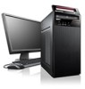
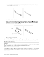
disk drive with the corresponding holes in the drive bay. Then, install the four screws to secure
 |
View all Lenovo ThinkCentre Edge 72 manuals
Add to My Manuals
Save this manual to your list of manuals |
Page 129 highlights
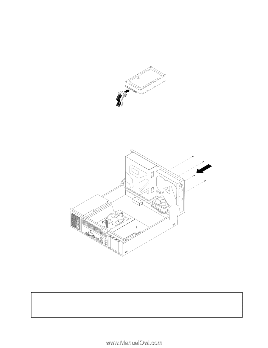
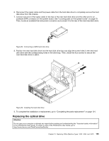
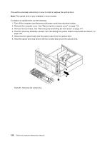
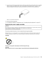
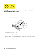
6. Disconnect the signal cable and the power cable from the hard disk drive to completely remove the hard disk drive from the chassis. 7. Connect one end of the signal cable to the rear of the new hard disk drive and the other end to an available SATA connector on the system board. See "Locating parts on the system board" on page 79. Then, locate an available five-wire power connector and connect it to the rear of the new hard disk drive. Figure 63. Connecting a SATA hard disk drive 8. Position the new hard disk drive into the hard disk drive bay and align the screw holes in the new hard disk drive with the corresponding holes in the drive bay. Then, install the four screws to secure the new hard disk drive in place. Figure 64. Installing the hard disk drive 9. To complete the installation or replacement, go to "Completing the parts replacement" on page 154. Replacing the optical drive Attention: Do not open your computer or attempt any repair before reading and understanding the "Important safety information" in the ThinkCentre User Guide. To obtain a copy of the ThinkCentre User Guide, go to: http://www.lenovo.com/ThinkCentreUserGuides Chapter 10. Replacing FRUs (Machine Types: 3493, 3496, and 3497) 125
-
 1
1 -
2
-
3
-
4
-
5
-
6
-
7
-
8
-
9
-
10
-
11
-
12
-
13
-
14
-
15
-
16
-
17
-
18
-
19
-
20
-
21
-
22
-
23
-
24
-
25
-
26
-
27
-
28
-
29
-
30
-
31
-
32
-
33
-
34
-
35
-
36
-
37
-
38
-
39
-
40
-
41
-
42
-
43
-
44
-
45
-
46
-
47
-
48
-
49
-
50
-
51
-
52
-
53
-
54
-
55
-
56
-
57
-
58
-
59
-
60
-
61
-
62
-
63
-
64
-
65
-
66
-
67
-
68
-
69
-
70
-
71
-
72
-
73
-
74
-
75
-
76
-
77
-
78
-
79
-
80
-
81
-
82
-
83
-
84
-
85
-
86
-
87
-
88
-
89
-
90
-
91
-
92
-
93
-
94
-
95
-
96
-
97
-
98
-
99
-
100
-
101
-
102
-
103
-
104
-
105
-
106
-
107
-
108
-
109
-
110
-
111
-
112
-
113
-
114
-
115
-
116
-
117
-
118
-
119
-
120
-
121
-
122
-
123
-
 124
124 -
 125
125 -
 126
126 -
 127
127 -
 128
128 -
 129
129 -
 130
130 -
 131
131 -
 132
132 -
 133
133 -
 134
134 -
135
-
136
-
137
-
138
-
139
-
140
-
141
-
142
-
143
-
144
-
145
-
146
-
147
-
148
-
149
-
150
-
151
-
152
-
153
-
154
-
155
-
156
-
157
-
158
-
159
-
160
-
161
-
162
-
163
-
164
-
165
-
166
-
167
-
168
-
169
-
170
 |
 |