Lenovo ThinkCentre Edge 72 Hardware Maintenance Manual (HMM) for ThinkCentre E - Page 133
following warnings are required for your safety and proper Underwriters Laboratories UL certification.
 |
View all Lenovo ThinkCentre Edge 72 manuals
Add to My Manuals
Save this manual to your list of manuals |
Page 133 highlights
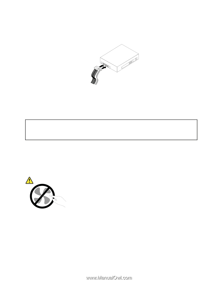
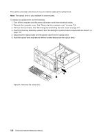
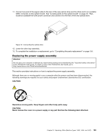
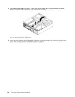
11. Connect one end of the signal cable to the rear of the new optical drive and the other end to an available SATA connector on the system board. See "Locating parts on the system board" on page 79. Then, locate an available five-wire power connector and connect it to the rear of the new optical drive. Figure 70. Connecting the optical drive 12. Lower the drive bay assembly. 13. To complete the installation or replacement, go to "Completing the parts replacement" on page 154. Replacing the power supply assembly Attention: Do not open your computer or attempt any repair before reading and understanding the "Important safety information" in the ThinkCentre User Guide. To obtain a copy of the ThinkCentre User Guide, go to: http://www.lenovo.com/ThinkCentreUserGuides This section provides instructions on how to replace the power supply assembly. Although there are no moving parts in your computer after the power cord has been disconnected, the following warnings are required for your safety and proper Underwriters Laboratories (UL) certification. CAUTION: Hazardous moving parts. Keep fingers and other body parts away. CAUTION: Never remove the cover on a power supply or any part that has the following label attached. Chapter 10. Replacing FRUs (Machine Types: 3493, 3496, and 3497) 129
-
 1
1 -
2
-
3
-
4
-
5
-
6
-
7
-
8
-
9
-
10
-
11
-
12
-
13
-
14
-
15
-
16
-
17
-
18
-
19
-
20
-
21
-
22
-
23
-
24
-
25
-
26
-
27
-
28
-
29
-
30
-
31
-
32
-
33
-
34
-
35
-
36
-
37
-
38
-
39
-
40
-
41
-
42
-
43
-
44
-
45
-
46
-
47
-
48
-
49
-
50
-
51
-
52
-
53
-
54
-
55
-
56
-
57
-
58
-
59
-
60
-
61
-
62
-
63
-
64
-
65
-
66
-
67
-
68
-
69
-
70
-
71
-
72
-
73
-
74
-
75
-
76
-
77
-
78
-
79
-
80
-
81
-
82
-
83
-
84
-
85
-
86
-
87
-
88
-
89
-
90
-
91
-
92
-
93
-
94
-
95
-
96
-
97
-
98
-
99
-
100
-
101
-
102
-
103
-
104
-
105
-
106
-
107
-
108
-
109
-
110
-
111
-
112
-
113
-
114
-
115
-
116
-
117
-
118
-
119
-
120
-
121
-
122
-
123
-
124
-
125
-
126
-
127
-
 128
128 -
 129
129 -
 130
130 -
 131
131 -
 132
132 -
 133
133 -
 134
134 -
 135
135 -
 136
136 -
 137
137 -
 138
138 -
139
-
140
-
141
-
142
-
143
-
144
-
145
-
146
-
147
-
148
-
149
-
150
-
151
-
152
-
153
-
154
-
155
-
156
-
157
-
158
-
159
-
160
-
161
-
162
-
163
-
164
-
165
-
166
-
167
-
168
-
169
-
170
 |
 |