Lenovo ThinkCentre Edge 72 Hardware Maintenance Manual (HMM) for ThinkCentre E - Page 148
Replacing the WiFi units
 |
View all Lenovo ThinkCentre Edge 72 manuals
Add to My Manuals
Save this manual to your list of manuals |
Page 148 highlights
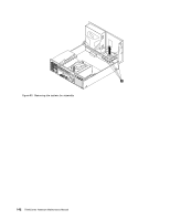
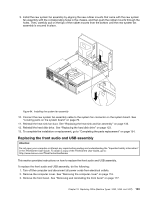
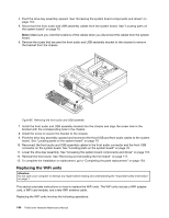
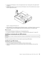
4. Pivot the drive bay assembly upward. See "Accessing the system board components and drives" on page 118. 5. Disconnect the front audio and USB assembly cables from the system board. See "Locating parts on the system board" on page 79. Note: Make sure you note the locations of the cables when you disconnect the cables from the system board. 6. Remove the screw that secures the front audio and USB assembly bracket to the chassis to remove the bracket from the chassis. Figure 85. Removing the front audio and USB assembly 7. Install the front audio and USB assembly bracket into the chassis and align the screw hole in the bracket with the corresponding hole in the chassis. 8. Install the screw to secure the bracket to the chassis. 9. Pivot the drive bay assembly upward and reconnect the front USB and front audio cables to the system board. See "Locating parts on the system board" on page 79. 10. Reconnect the front audio and USB assembly cables to the front audio connector and the front USB connector on the system board. See "Locating parts on the system board" on page 79. 11. Lower the drive bay assembly. See "Accessing the system board components and drives" on page 118. 12. Reinstall the front bezel. See "Removing and reinstalling the front bezel" on page 117. 13. To complete the installation or replacement, go to "Completing the parts replacement" on page 154. Replacing the WiFi units Attention: Do not open your computer or attempt any repair before reading and understanding the "Important safety information" on page 1. This section provides instructions on how to replace the WiFi units. The WiFi units include a WiFi adapter card, a WiFi card module, and a rear WiFi antenna cable. Replacing the WiFi units involves the following operations: 144 ThinkCentre Hardware Maintenance Manual
-
 1
1 -
2
-
3
-
4
-
5
-
6
-
7
-
8
-
9
-
10
-
11
-
12
-
13
-
14
-
15
-
16
-
17
-
18
-
19
-
20
-
21
-
22
-
23
-
24
-
25
-
26
-
27
-
28
-
29
-
30
-
31
-
32
-
33
-
34
-
35
-
36
-
37
-
38
-
39
-
40
-
41
-
42
-
43
-
44
-
45
-
46
-
47
-
48
-
49
-
50
-
51
-
52
-
53
-
54
-
55
-
56
-
57
-
58
-
59
-
60
-
61
-
62
-
63
-
64
-
65
-
66
-
67
-
68
-
69
-
70
-
71
-
72
-
73
-
74
-
75
-
76
-
77
-
78
-
79
-
80
-
81
-
82
-
83
-
84
-
85
-
86
-
87
-
88
-
89
-
90
-
91
-
92
-
93
-
94
-
95
-
96
-
97
-
98
-
99
-
100
-
101
-
102
-
103
-
104
-
105
-
106
-
107
-
108
-
109
-
110
-
111
-
112
-
113
-
114
-
115
-
116
-
117
-
118
-
119
-
120
-
121
-
122
-
123
-
124
-
125
-
126
-
127
-
128
-
129
-
130
-
131
-
132
-
133
-
134
-
135
-
136
-
137
-
138
-
139
-
140
-
141
-
142
-
 143
143 -
 144
144 -
 145
145 -
 146
146 -
 147
147 -
 148
148 -
 149
149 -
 150
150 -
 151
151 -
 152
152 -
 153
153 -
154
-
155
-
156
-
157
-
158
-
159
-
160
-
161
-
162
-
163
-
164
-
165
-
166
-
167
-
168
-
169
-
170
 |
 |
