Lenovo ThinkCentre Edge 72 Hardware Maintenance Manual (HMM) for ThinkCentre E - Page 145
Replacing the system fan assembly
 |
View all Lenovo ThinkCentre Edge 72 manuals
Add to My Manuals
Save this manual to your list of manuals |
Page 145 highlights
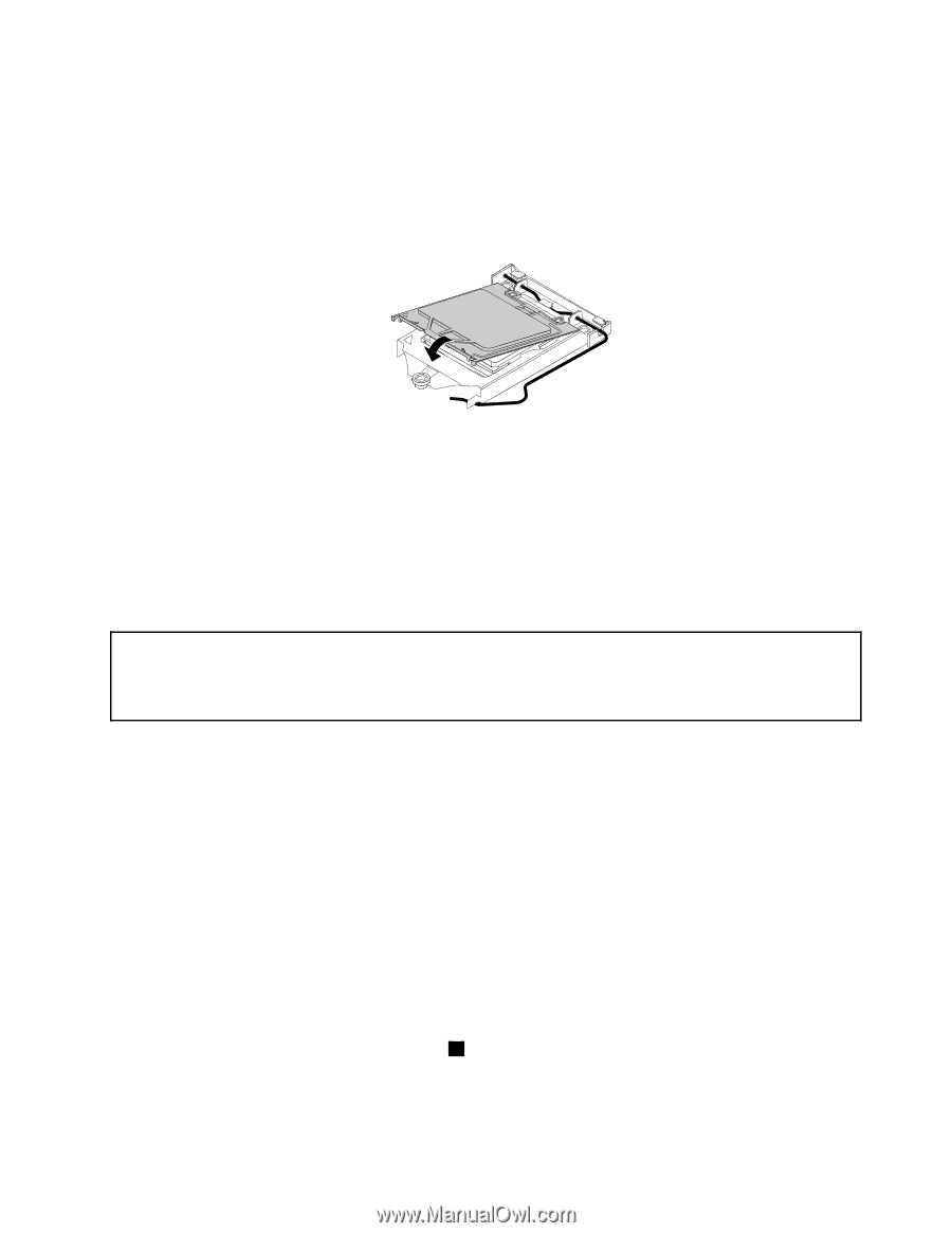
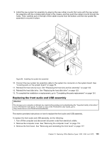
2. Grasp the microprocessor on the sides and lift it straight up and out of the socket. Do not touch the contacts on the microprocessor socket. 3. Lower the microprocessor retainer, and then lower the lever to secure the retainer. Make sure the lever is locked into position. 4. Note the orientation of the socket cover, and install one side of the socket cover into the microprocessor socket. Figure 82. Installing one side of the socket cover into the microprocessor socket Note: Your microprocessor socket and cover might look slightly different from the illustration. 5. Carefully press the other side of the socket cover downward until the socket cover snaps into position. 6. Carefully check the four corners of the socket cover to make sure that the cover is secured in the microprocessor socket. 7. Follow any additional instructions included with the replacement part you received. Replacing the system fan assembly Attention: Do not open your computer or attempt any repair before reading and understanding the "Important safety information" in the ThinkCentre User Guide. To obtain a copy of the ThinkCentre User Guide, go to: http://www.lenovo.com/ThinkCentreUserGuides This section provides instructions on how to replace the system fan assembly. To replace the system fan assembly, do the following: 1. Turn off the computer and disconnect all power cords from electrical outlets. 2. Remove the computer cover. See "Removing the computer cover" on page 116. 3. Remove the front bezel. See "Removing and reinstalling the front bezel" on page 117. 4. Pivot the drive bay assembly upward to gain access to the system fan assembly. See "Accessing the system board components and drives" on page 118. 5. Remove the hard disk drive for easier access to the system fan assembly. See "Replacing the hard disk drive" on page 123. 6. Remove the heat sink fan duct. See "Replacing the heat sink and fan assembly" on page 133. 7. Note the cable routing and disconnect the system fan assembly cable from the power fan connector on the system board. See "Locating parts on the system board" on page 79. 8. The system fan assembly is attached to the chassis by four rubber mounts. Remove the system fan assembly by cutting the four rubber mounts 1 and lifting the system fan assembly out of the chassis. Note: The new system fan assembly will have four new rubber mounts attached. Chapter 10. Replacing FRUs (Machine Types: 3493, 3496, and 3497) 141
-
 1
1 -
2
-
3
-
4
-
5
-
6
-
7
-
8
-
9
-
10
-
11
-
12
-
13
-
14
-
15
-
16
-
17
-
18
-
19
-
20
-
21
-
22
-
23
-
24
-
25
-
26
-
27
-
28
-
29
-
30
-
31
-
32
-
33
-
34
-
35
-
36
-
37
-
38
-
39
-
40
-
41
-
42
-
43
-
44
-
45
-
46
-
47
-
48
-
49
-
50
-
51
-
52
-
53
-
54
-
55
-
56
-
57
-
58
-
59
-
60
-
61
-
62
-
63
-
64
-
65
-
66
-
67
-
68
-
69
-
70
-
71
-
72
-
73
-
74
-
75
-
76
-
77
-
78
-
79
-
80
-
81
-
82
-
83
-
84
-
85
-
86
-
87
-
88
-
89
-
90
-
91
-
92
-
93
-
94
-
95
-
96
-
97
-
98
-
99
-
100
-
101
-
102
-
103
-
104
-
105
-
106
-
107
-
108
-
109
-
110
-
111
-
112
-
113
-
114
-
115
-
116
-
117
-
118
-
119
-
120
-
121
-
122
-
123
-
124
-
125
-
126
-
127
-
128
-
129
-
130
-
131
-
132
-
133
-
134
-
135
-
136
-
137
-
138
-
139
-
 140
140 -
 141
141 -
 142
142 -
 143
143 -
 144
144 -
 145
145 -
 146
146 -
 147
147 -
 148
148 -
 149
149 -
 150
150 -
151
-
152
-
153
-
154
-
155
-
156
-
157
-
158
-
159
-
160
-
161
-
162
-
163
-
164
-
165
-
166
-
167
-
168
-
169
-
170
 |
 |