Lenovo ThinkCentre M72z Hardware Maintenance Manual (HMM) for ThinkCentre M72z - Page 111
Disconnect the LCD panel cable from the system board. See System board parts and connectors
 |
View all Lenovo ThinkCentre M72z manuals
Add to My Manuals
Save this manual to your list of manuals |
Page 111 highlights
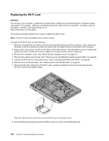
Figure 42. Removing the frame stand 5. Locate the LCD panel in the computer. See "Locating major FRUs and CRUs" on page 66. 6. Remove the optical drive. See "Replacing the optical drive" on page 82. 7. Remove the inverter. See "Replacing the inverter" on page 97. 8. Remove the rear I/O assembly. See "Replacing the rear I/O assembly" on page 84. 9. Remove the system board shield. See "Removing and reinstalling the system board shield" on page 86. 10. Disconnect the LCD panel cable from the system board. See "System board parts and connectors" on page 70. Figure 43. Disconnect the LCD panel cable from the system board Chapter 9. Replacing FRUs 105
-
 1
1 -
2
-
3
-
4
-
5
-
6
-
7
-
8
-
9
-
10
-
11
-
12
-
13
-
14
-
15
-
16
-
17
-
18
-
19
-
20
-
21
-
22
-
23
-
24
-
25
-
26
-
27
-
28
-
29
-
30
-
31
-
32
-
33
-
34
-
35
-
36
-
37
-
38
-
39
-
40
-
41
-
42
-
43
-
44
-
45
-
46
-
47
-
48
-
49
-
50
-
51
-
52
-
53
-
54
-
55
-
56
-
57
-
58
-
59
-
60
-
61
-
62
-
63
-
64
-
65
-
66
-
67
-
68
-
69
-
70
-
71
-
72
-
73
-
74
-
75
-
76
-
77
-
78
-
79
-
80
-
81
-
82
-
83
-
84
-
85
-
86
-
87
-
88
-
89
-
90
-
91
-
92
-
93
-
94
-
95
-
96
-
97
-
98
-
99
-
100
-
101
-
102
-
103
-
104
-
105
-
 106
106 -
 107
107 -
 108
108 -
 109
109 -
 110
110 -
 111
111 -
 112
112 -
 113
113 -
 114
114 -
 115
115 -
 116
116 -
117
-
118
-
119
-
120
-
121
-
122
-
123
-
124
-
125
-
126
 |
 |
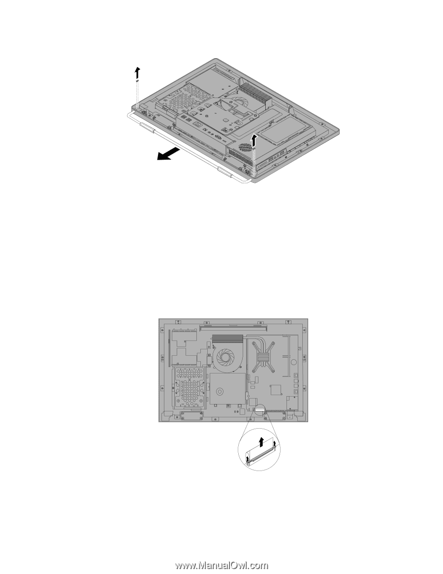
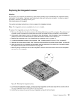
Figure 42. Removing the frame stand
5. Locate the LCD panel in the computer. See “Locating major FRUs and CRUs” on page 66.
6. Remove the optical drive. See “Replacing the optical drive” on page 82.
7. Remove the inverter. See “Replacing the inverter” on page 97.
8. Remove the rear I/O assembly. See “Replacing the rear I/O assembly” on page 84.
9. Remove the system board shield. See “Removing and reinstalling the system board shield” on page 86.
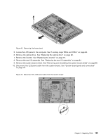
10. Disconnect the LCD panel cable from the system board. See “System board parts and connectors”
on page 70.
Figure 43. Disconnect the LCD panel cable from the system board
Chapter 9
.
Replacing FRUs
105