Lenovo ThinkCentre M72z Hardware Maintenance Manual (HMM) for ThinkCentre M72z - Page 99
microprocessor in the socket.
 |
View all Lenovo ThinkCentre M72z manuals
Add to My Manuals
Save this manual to your list of manuals |
Page 99 highlights
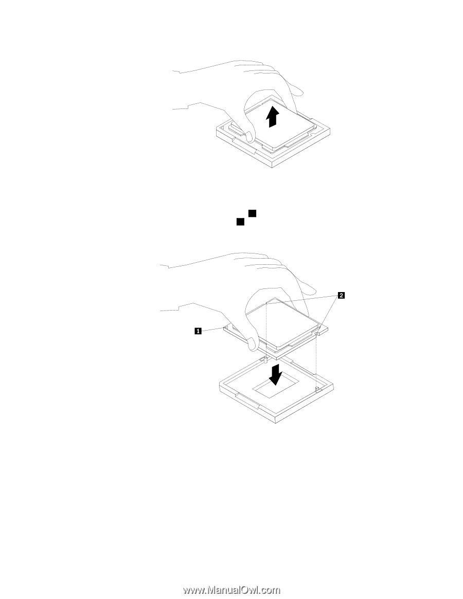
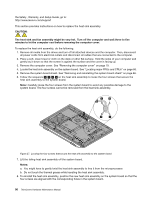
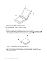
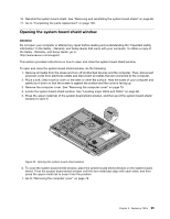
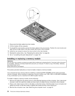
Figure 30. Removing the microprocessor 9. Make sure that the small handle is in the raised position and the microprocessor retainer is fully open. 10. Hold the new microprocessor and align the notches 2 on it with the alignment keys in the microprocessor socket, or align the small triangle 1 on one corner of the new microprocessor with the corresponding beveled corner of the microprocessor socket. Figure 31. Installing the microprocessor 11. Lower the new microprocessor straight down into the microprocessor socket on the system board. 12. Close the microprocessor retainer and lock it into position with the small handle to secure the new microprocessor in the socket. 13. Reinstall the heat sink assembly. See "Replacing the heat sink assembly" on page 89. 14. Reinstall the system board shield. See "Removing and reinstalling the system board shield" on page 86. 15. Go to "Completing the parts replacement" on page 109. Chapter 9. Replacing FRUs 93
-
 1
1 -
2
-
3
-
4
-
5
-
6
-
7
-
8
-
9
-
10
-
11
-
12
-
13
-
14
-
15
-
16
-
17
-
18
-
19
-
20
-
21
-
22
-
23
-
24
-
25
-
26
-
27
-
28
-
29
-
30
-
31
-
32
-
33
-
34
-
35
-
36
-
37
-
38
-
39
-
40
-
41
-
42
-
43
-
44
-
45
-
46
-
47
-
48
-
49
-
50
-
51
-
52
-
53
-
54
-
55
-
56
-
57
-
58
-
59
-
60
-
61
-
62
-
63
-
64
-
65
-
66
-
67
-
68
-
69
-
70
-
71
-
72
-
73
-
74
-
75
-
76
-
77
-
78
-
79
-
80
-
81
-
82
-
83
-
84
-
85
-
86
-
87
-
88
-
89
-
90
-
91
-
92
-
93
-
 94
94 -
 95
95 -
 96
96 -
 97
97 -
 98
98 -
 99
99 -
 100
100 -
 101
101 -
 102
102 -
 103
103 -
 104
104 -
105
-
106
-
107
-
108
-
109
-
110
-
111
-
112
-
113
-
114
-
115
-
116
-
117
-
118
-
119
-
120
-
121
-
122
-
123
-
124
-
125
-
126
 |
 |