Lenovo ThinkCentre M72z Hardware Maintenance Manual (HMM) for ThinkCentre M72z - Page 112
chassis. Reinstall the four screws to secure the LCD panel to the chassis.
 |
View all Lenovo ThinkCentre M72z manuals
Add to My Manuals
Save this manual to your list of manuals |
Page 112 highlights
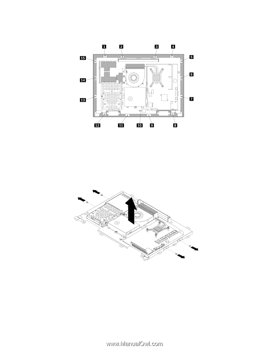
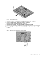
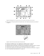
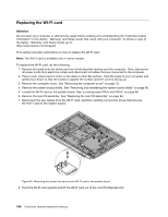
11. Remove all the 15 screws that secure the computer main bracket to the front bezel. Figure 44. Removing all the 15 screws that secure the computer main bracket to the front bezel 12. Note the locations of all cable connections that prevent you from lifting the computer main bracket, and disconnect all cables. See "System board parts and connectors" on page 70. 13. Remove the integrated camera. See "Replacing the integrated camera" on page 101. 14. Lift the computer main bracket off the front bezel. 15. Remove the four screws that secure the chassis to the LCD panel, and then lift the chassis out of the computer to get assess to the LCD panel. Figure 45. Removing the four screws that secure the LCD panel 16. Place the computer chassis over the new LCD panel so that the four screw holes align with those in the chassis. Reinstall the four screws to secure the LCD panel to the chassis. 17. Position the computer main bracket over the LCD panel. Make sure the screw holes in the computer main bracket align with those in the front bezel. 18. Reinstall all the 15 screws that secure the computer main bracket to the front bezel. 106 ThinkCentre Hardware Maintenance Manual
-
 1
1 -
2
-
3
-
4
-
5
-
6
-
7
-
8
-
9
-
10
-
11
-
12
-
13
-
14
-
15
-
16
-
17
-
18
-
19
-
20
-
21
-
22
-
23
-
24
-
25
-
26
-
27
-
28
-
29
-
30
-
31
-
32
-
33
-
34
-
35
-
36
-
37
-
38
-
39
-
40
-
41
-
42
-
43
-
44
-
45
-
46
-
47
-
48
-
49
-
50
-
51
-
52
-
53
-
54
-
55
-
56
-
57
-
58
-
59
-
60
-
61
-
62
-
63
-
64
-
65
-
66
-
67
-
68
-
69
-
70
-
71
-
72
-
73
-
74
-
75
-
76
-
77
-
78
-
79
-
80
-
81
-
82
-
83
-
84
-
85
-
86
-
87
-
88
-
89
-
90
-
91
-
92
-
93
-
94
-
95
-
96
-
97
-
98
-
99
-
100
-
101
-
102
-
103
-
104
-
105
-
106
-
 107
107 -
 108
108 -
 109
109 -
 110
110 -
 111
111 -
 112
112 -
 113
113 -
 114
114 -
 115
115 -
 116
116 -
 117
117 -
118
-
119
-
120
-
121
-
122
-
123
-
124
-
125
-
126
 |
 |