Lenovo ThinkCentre M72z Hardware Maintenance Manual (HMM) for ThinkCentre M72z - Page 96
system board. The four screws cannot be removed from the heat sink assembly. - touch screen
 |
View all Lenovo ThinkCentre M72z manuals
Add to My Manuals
Save this manual to your list of manuals |
Page 96 highlights
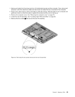
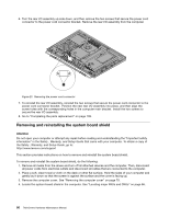
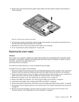
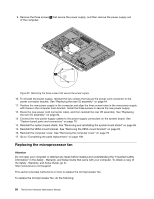
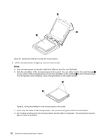
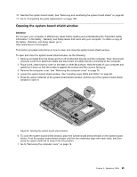
the Safety , Warranty, and Setup Guide, go to: http://www.lenovo.com/support This section provides instructions on how to replace the heat sink assembly. CAUTION: The heat sink and fan assembly might be very hot. Turn off the computer and wait three to five minutes to let the computer cool before removing the computer cover. To replace the heat sink assembly, do the following: 1. Remove all media from the drives and turn off all attached devices and the computer. Then, disconnect all power cords from electrical outlets and disconnect all cables that are connected to the computer. 2. Place a soft, clean towel or cloth on the desk or other flat surface. Hold the sides of your computer and gently lay it down so that the screen is against the surface and the cover is facing up. 3. Remove the computer cover. See "Removing the computer cover" on page 79. 4. Locate the heat sink assembly on the system board. See "Locating major FRUs and CRUs" on page 66. 5. Remove the system board shield. See "Removing and reinstalling the system board shield" on page 86. 6. Follow the sequence 1 , 2 , 3 , 4 on the heat sink assembly to loose the four screws that secure the heat sink assembly to the system board. Note: Carefully loose the four screws from the system board to avoid any possible damage to the system board. The four screws cannot be removed from the heat sink assembly. Figure 27. Loosing the four screws that secure the heat sink assembly to the system board 7. Lift the failing heat sink assembly off the system board. Notes: a. You might have to gently twist the heat sink assembly to free it from the microprocessor. b. Do not touch the thermal grease while handling the heat sink assembly. 8. To reinstall the heat sink assembly, position the new heat sink assembly on the system board so that the four screws are aligned with the corresponding holes in the system board. 90 ThinkCentre Hardware Maintenance Manual
-
 1
1 -
2
-
3
-
4
-
5
-
6
-
7
-
8
-
9
-
10
-
11
-
12
-
13
-
14
-
15
-
16
-
17
-
18
-
19
-
20
-
21
-
22
-
23
-
24
-
25
-
26
-
27
-
28
-
29
-
30
-
31
-
32
-
33
-
34
-
35
-
36
-
37
-
38
-
39
-
40
-
41
-
42
-
43
-
44
-
45
-
46
-
47
-
48
-
49
-
50
-
51
-
52
-
53
-
54
-
55
-
56
-
57
-
58
-
59
-
60
-
61
-
62
-
63
-
64
-
65
-
66
-
67
-
68
-
69
-
70
-
71
-
72
-
73
-
74
-
75
-
76
-
77
-
78
-
79
-
80
-
81
-
82
-
83
-
84
-
85
-
86
-
87
-
88
-
89
-
90
-
 91
91 -
 92
92 -
 93
93 -
 94
94 -
 95
95 -
 96
96 -
 97
97 -
 98
98 -
 99
99 -
 100
100 -
 101
101 -
102
-
103
-
104
-
105
-
106
-
107
-
108
-
109
-
110
-
111
-
112
-
113
-
114
-
115
-
116
-
117
-
118
-
119
-
120
-
121
-
122
-
123
-
124
-
125
-
126
 |
 |
