Lenovo ThinkCentre M72z Hardware Maintenance Manual (HMM) for ThinkCentre M72z - Page 113
Reinstall the foot stands. See Removing and reinstalling the frame stand
 |
View all Lenovo ThinkCentre M72z manuals
Add to My Manuals
Save this manual to your list of manuals |
Page 113 highlights
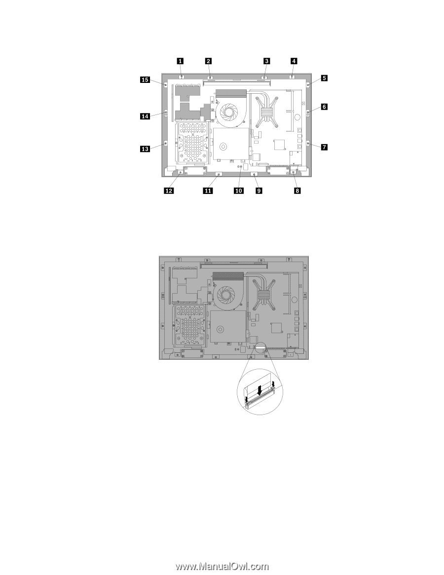
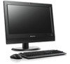
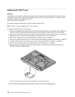
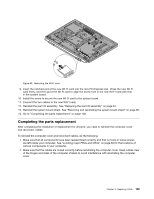
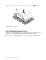
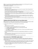
Figure 46. Reinstalling all the 15 screws that secure the computer main bracket to the front bezel 19. Reconnect the LCD panel cable from the system board. See "System board parts and connectors" on page 70. Figure 47. Reconnect the LCD panel cable to the system board 20. Reinstall the integrated camera. See "Replacing the integrated camera" on page 101. 21. Reinstall the rear I/O assembly. See "Replacing the rear I/O assembly" on page 84. 22. Reinstall the system board shield. See "Removing and reinstalling the system board shield" on page 86. 23. Reinstall the foot stands. See "Removing and reinstalling the frame stand" on page 76. 24. Connect all the cables that were disconnected. See "System board parts and connectors" on page 70. 25. Go to "Completing the parts replacement" on page 109. Chapter 9. Replacing FRUs 107
-
 1
1 -
2
-
3
-
4
-
5
-
6
-
7
-
8
-
9
-
10
-
11
-
12
-
13
-
14
-
15
-
16
-
17
-
18
-
19
-
20
-
21
-
22
-
23
-
24
-
25
-
26
-
27
-
28
-
29
-
30
-
31
-
32
-
33
-
34
-
35
-
36
-
37
-
38
-
39
-
40
-
41
-
42
-
43
-
44
-
45
-
46
-
47
-
48
-
49
-
50
-
51
-
52
-
53
-
54
-
55
-
56
-
57
-
58
-
59
-
60
-
61
-
62
-
63
-
64
-
65
-
66
-
67
-
68
-
69
-
70
-
71
-
72
-
73
-
74
-
75
-
76
-
77
-
78
-
79
-
80
-
81
-
82
-
83
-
84
-
85
-
86
-
87
-
88
-
89
-
90
-
91
-
92
-
93
-
94
-
95
-
96
-
97
-
98
-
99
-
100
-
101
-
102
-
103
-
104
-
105
-
106
-
107
-
 108
108 -
 109
109 -
 110
110 -
 111
111 -
 112
112 -
 113
113 -
 114
114 -
 115
115 -
 116
116 -
 117
117 -
 118
118 -
119
-
120
-
121
-
122
-
123
-
124
-
125
-
126
 |
 |