Lexmark 4076 Execjet II Service Manual - Page 25
Operator Panel Service Check, Diagnostic Information, FRU OR PROCEDURE, ACTION
 |
View all Lexmark 4076 Execjet II manuals
Add to My Manuals
Save this manual to your list of manuals |
Page 25 highlights
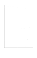
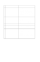
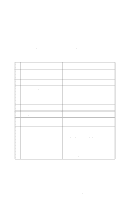
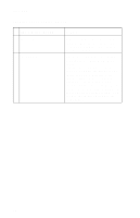
4076-0XX Operator Panel Service Check FRU OR PROCEDURE 1 Power Supply 2 System Board 3 Operator Panel Cover 4 Operator Panel Card Operator Panel Cable ACTION Disconnect J11 from the system board and check the following voltages on the power supply cable: J11-1 to GND = +5V dc J11-3 to GND = +24V dc If you do not have correct voltage, replace the power supply. Be sure to unplug the machine before you reconnect the power supply to the system board. Turn the printer on. Check for +5 V dc at test point CE/TP near the operator panel connector on the system board The operator panel cover actuates the operator panel sensor on the operator panel. Check the cover for any broken parts. Check the operator panel sensor for dirt. Check the operator panel cable for continuity. If the cable is good, replace the operator panel. If the symptom remains, replace the system board. Diagnostic Information 13
-
 1
1 -
2
-
3
-
4
-
5
-
6
-
7
-
8
-
9
-
10
-
11
-
12
-
13
-
14
-
15
-
16
-
17
-
18
-
19
-
 20
20 -
 21
21 -
 22
22 -
 23
23 -
 24
24 -
 25
25 -
 26
26 -
 27
27 -
 28
28 -
 29
29 -
 30
30 -
31
-
32
-
33
-
34
-
35
-
36
-
37
-
38
-
39
-
40
-
41
-
42
-
43
-
44
-
45
-
46
-
47
-
48
-
49
-
50
-
51
-
52
-
53
-
54
-
55
-
56
-
57
-
58
-
59
-
60
-
61
-
62
-
63
-
64
-
65
-
66
-
67
-
68
-
69
-
70
-
71
-
72
-
73
-
74
-
75
-
76
-
77
-
78
-
79
-
80
-
81
-
82
-
83
-
84
-
85
-
86
-
87
-
88
-
89
 |
 |
