| Section |
Page |
| Contents |
2 |
| Safety information |
7 |
| Learning about the printer |
9 |
| Basic functions of the scanner |
9 |
| Finding information about the printer |
9 |
| Selecting a location for the printer and the scanner |
10 |
| Printer configurations |
11 |
| Understanding the ADF and scanner glass |
12 |
| Understanding the scanner control panel |
13 |
| Understanding the home screen |
14 |
| Understanding the home screen |
14 |
| Using the touch-screen buttons |
15 |
| Customizing the home screen |
18 |
| Finding the IP address of the scanner |
18 |
| Accessing the Embedded Web Server |
18 |
| Activating the home screen applications |
19 |
| Exporting and importing a configuration using the Embedded Web Server |
21 |
| Additional printer setup |
22 |
| Installing a scanner communications card in the printer |
22 |
| Installing internal options in the scanner |
26 |
| Available internal options |
26 |
| Accessing the system board |
26 |
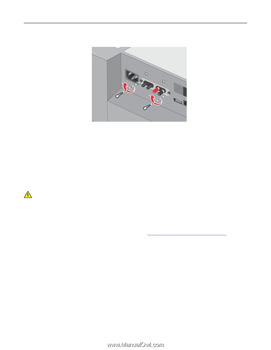
| Installing an Internal Solutions Port |
31 |
| Installing a flash memory or firmware card |
38 |
| Installing a memory card |
39 |
| Installing hardware options |
41 |
| Order of installation |
41 |
| Installing optional paper drawers |
42 |
| Attaching cables |
43 |
| Verifying printer setup |
44 |
| Printing a menu settings page |
44 |
| Printing a network setup page |
45 |
| Setting up the scanner software |
45 |
| Installing the scanner |
45 |
| Adding available options in the print driver |
45 |
| Networking |
46 |
| Preparing to set up the scanner on an Ethernet network |
46 |
| Preparing to set up the scanner on a wireless network |
46 |
| Installing the scanner on a wireless network (Windows) |
47 |
| Installing the scanner on a wireless network (Macintosh) |
50 |
| Changing port settings after installing a new network ISP |
53 |
| Setting up serial printing (Windows only) |
53 |
| Minimizing your printer's environmental impact |
55 |
| Saving paper and toner |
55 |
| Using recycled paper |
55 |
| Conserving supplies |
55 |
| Saving energy |
56 |
| Using Eco-Mode |
56 |
| Reducing scanner noise |
56 |
| Adjusting Sleep Mode |
57 |
| Adjusting the brightness of the display |
57 |
| Recycling |
58 |
| Recycling Lexmark products |
58 |
| Recycling Lexmark packaging |
58 |
| Returning Lexmark cartridges for reuse or recycling |
58 |
| Loading paper and specialty media |
60 |
| Loading the standard or optional 250- or 550-sheet tray |
60 |
| Loading the 2000-sheet tray |
63 |
| Loading the multipurpose feeder |
66 |
| Loading the envelope feeder |
69 |
| Loading business cards into the ADF |
70 |
| Setting the paper size and type |
71 |
| Setting the paper size and type for difficult media |
71 |
| Setting the paper size and type for the printer |
72 |
| Configuring Universal paper settings |
73 |
| Setting the ADF to detect multiple paper feeds |
73 |
| Linking and unlinking trays |
73 |
| Linking trays |
73 |
| Unlinking trays |
74 |
| Creating a custom name for a paper type |
74 |
| Assigning a custom paper type name |
74 |
| Paper and specialty media guidelines |
75 |
| Paper guidelines |
75 |
| Paper characteristics |
75 |
| Selecting paper |
76 |
| Selecting preprinted forms and letterhead |
76 |
| Using recycled paper and other office papers |
76 |
| Storing paper |
78 |
| Supported paper sizes, types, and weights |
78 |
| Supported paper sizes |
78 |
| Supported paper types and weights |
81 |
| Printing |
83 |
| Printing a document |
83 |
| Printing a document |
83 |
| Printing from a mobile device |
83 |
| Printing from a flash drive |
84 |
| Printing from a flash drive |
84 |
| Supported flash drives and file types |
85 |
| Printing on specialty media |
86 |
| Tips on using letterhead |
86 |
| Tips on using transparencies |
86 |
| Tips on using envelopes |
86 |
| Tips on using labels |
87 |
| Tips on using card stock |
88 |
| Printing confidential and other held jobs |
88 |
| Storing print jobs in the scanner |
88 |
| Printing confidential and other held jobs |
89 |
| Printing information pages |
89 |
| Printing a font sample list |
89 |
| Printing a directory list |
90 |
| Printing print quality test pages |
90 |
| Adjusting toner darkness |
90 |
| Canceling a print job |
90 |
| Canceling a print job from the scanner control panel |
90 |
| Canceling a print job from the computer |
91 |
| Copying |
92 |
| Making copies |
92 |
| Making a quick copy |
92 |
| Copying using the ADF or scanner glass |
92 |
| Copying photos |
93 |
| Copying on transparencies or letterhead |
93 |
| Customizing copy settings |
93 |
| Copying to a different size |
93 |
| Making copies using paper from a selected tray |
93 |
| Copying different paper sizes |
94 |
| Copying on both sides of the paper (two-sided) |
94 |
| Reducing or enlarging copies |
94 |
| Adjusting copy quality |
95 |
| Collating copies |
95 |
| Placing separator sheets between copies |
95 |
| Copying multiple pages onto a single sheet |
95 |
| Creating a custom copy job |
96 |
| Placing a header or footer on pages |
96 |
| Canceling a copy job while pages are being printed |
96 |
| Understanding the copy options |
97 |
| Copy from |
97 |
| Copy to |
97 |
| Scale |
97 |
| Darkness |
97 |
| Sides (Duplex) |
97 |
| Collate |
97 |
| Copies |
97 |
| Content |
97 |
| Save As Shortcut |
98 |
| Using the advanced options |
98 |
| E-mailing |
99 |
| Getting ready to e-mail |
99 |
| Setting up the e-mail function |
99 |
| Configuring e-mail settings |
99 |
| Creating an e-mail shortcut |
100 |
| Creating an e-mail shortcut using the Embedded Web Server |
100 |
| Creating an e-mail shortcut using the touch screen |
100 |
| E-mailing a document |
101 |
| Sending an e-mail using the touch screen |
101 |
| Sending an e-mail using a shortcut number |
101 |
| Sending an e-mail using the address book |
101 |
| Customizing e-mail settings |
102 |
| Adding e-mail subject and message information |
102 |
| Changing the output file type |
102 |
| Canceling an e-mail |
102 |
| Understanding the e-mail options |
102 |
| Recipient(s) |
102 |
| Subject |
102 |
| Message |
103 |
| File Name |
103 |
| Original Size |
103 |
| Resolution |
103 |
| Color |
103 |
| Content |
103 |
| Darkness |
103 |
| Send As |
103 |
| Page Setup |
104 |
| Scan Preview |
104 |
| Using the advanced options |
104 |
| Faxing |
105 |
| Getting the scanner ready to fax |
105 |
| Initial fax setup |
106 |
| Connecting to an analog telephone line |
107 |
| Connecting to a DSL service |
107 |
| Connecting to a PBX or ISDN system |
107 |
| Connecting to a distinctive ring service |
108 |
| Connecting to an adapter for your country or region |
108 |
| Setting the outgoing fax or station name and number |
109 |
| Setting the date and time |
110 |
| Configuring the scanner to observe daylight saving time |
110 |
| Creating shortcuts |
110 |
| Creating a fax destination shortcut using the Embedded Web Server |
110 |
| Creating a fax destination shortcut using the touch screen |
111 |
| Sending a fax |
111 |
| Sending a fax using the touch screen |
111 |
| Sending a fax using the computer |
112 |
| Sending a fax using shortcuts |
112 |
| Sending a fax using the address book |
113 |
| Using shortcuts and the address book |
113 |
| Using fax shortcuts |
113 |
| Using the address book |
113 |
| Customizing fax settings |
114 |
| Changing the fax resolution |
114 |
| Making a fax lighter or darker |
114 |
| Sending a fax at a scheduled time |
114 |
| Viewing a fax log |
115 |
| Blocking junk faxes |
115 |
| Canceling an outgoing fax |
115 |
| Canceling a fax while the original documents are still scanning |
115 |
| Canceling a fax after the original documents have been scanned to memory |
116 |
| Understanding the fax options |
116 |
| Content |
116 |
| Resolution |
116 |
| Darkness |
116 |
| Color |
116 |
| Page Setup |
116 |
| Scan Preview |
117 |
| Using the advanced options |
117 |
| Holding and forwarding faxes |
117 |
| Holding faxes |
117 |
| Forwarding a fax |
117 |
| Scanning |
119 |
| Scanning to an FTP address |
119 |
| Creating shortcuts |
119 |
| Creating an FTP shortcut using the Embedded Web Server |
119 |
| Creating an FTP shortcut using the scanner control panel |
120 |
| Scanning to an FTP address |
120 |
| Scanning to an FTP address using the scanner control panel |
120 |
| Scanning to an FTP address using a shortcut number |
120 |
| Scanning to an FTP using the address book |
121 |
| Scanning to a computer or to a flash drive |
121 |
| Scanning to a computer using the Embedded Web Server |
121 |
| Scanning to a flash drive |
122 |
| Understanding the Scan Center features |
122 |
| Using the ScanBack Utility |
123 |
| Understanding the FTP options |
123 |
| FTP |
123 |
| File Name |
123 |
| Original Size |
124 |
| Send As |
124 |
| Color |
124 |
| Resolution |
124 |
| Darkness |
124 |
| Page Setup |
124 |
| Content |
124 |
| Scan Preview |
124 |
| Using the advanced options |
125 |
| Understanding the printer menus |
126 |
| Menus list |
126 |
| Supplies menu |
127 |
| Paper menu |
127 |
| Default Source menu |
127 |
| Paper Size/Type menu |
128 |
| Configure MP menu |
131 |
| Envelope Enhance |
132 |
| Substitute Size menu |
132 |
| Paper Texture menu |
132 |
| Paper Weight menu |
134 |
| Paper Loading menu |
135 |
| Custom Types menu |
137 |
| Custom Names menu |
137 |
| Custom Scan Sizes menu |
138 |
| Custom Bin Names menu |
138 |
| Universal Setup menu |
139 |
| Bin Setup menu |
139 |
| Reports menu |
141 |
| Reports menu |
141 |
| Network/Ports menu |
142 |
| Active NIC menu |
142 |
| Standard Network or Network [x] menu |
142 |
| Network Reports menu |
144 |
| Network Card menu |
144 |
| TCP/IP menu |
145 |
| IPv6 menu |
146 |
| Wireless menu |
147 |
| AppleTalk menu |
147 |
| Standard USB menu |
148 |
| Parallel [x] menu |
150 |
| Serial [x] menu |
152 |
| SMTP Setup menu |
154 |
| Security menu |
155 |
| Editing Security Setups menu |
155 |
| Miscellaneous Security Settings menu |
156 |
| Confidential Print menu |
157 |
| Erase Temporary Data Files menu |
157 |
| Security Audit Log menu |
158 |
| Set Date and Time menu |
160 |
| Settings menu |
161 |
| General Settings menu |
161 |
| Copy Settings menu |
168 |
| Fax Settings menu |
172 |
| Fax Mode (Analog Fax Setup) menu |
172 |
| Fax Mode (Fax Server Setup) menu |
181 |
| E-mail Settings menu |
184 |
| FTP Settings menu |
189 |
| Flash Drive menu |
193 |
| Flash Drive menu |
193 |
| Print Settings |
199 |
| Setup menu |
199 |
| Finishing menu |
201 |
| Quality menu |
203 |
| Job Accounting menu |
204 |
| Utilities menu |
205 |
| XPS menu |
206 |
| PDF menu |
206 |
| PostScript menu |
207 |
| PCL Emul menu |
207 |
| HTML menu |
210 |
| Image menu |
211 |
| Help menu |
211 |
| Maintaining the scanner |
213 |
| Cleaning the exterior of the scanner |
213 |
| Cleaning the scanner glass |
213 |
| Cleaning the ADF glass |
214 |
| Cleaning the ADF parts |
214 |
| Cleaning the touch screen |
218 |
| Storing supplies |
218 |
| Checking the status of supplies |
219 |
| Checking the status of supplies from the control panel |
219 |
| Checking the status of supplies from a network computer |
219 |
| Ordering supplies |
219 |
| Ordering scanner supplies |
219 |
| Ordering a cleaning kit |
219 |
| Ordering a separator pad |
219 |
| Ordering printer supplies |
220 |
| Ordering print cartridges |
220 |
| Ordering a maintenance kit |
221 |
| Ordering charge rolls |
221 |
| Ordering a fuser |
222 |
| Ordering a fuser wiper |
222 |
| Ordering pick rollers |
222 |
| Ordering staple cartridges |
222 |
| Ordering a transfer roll assembly |
222 |
| Replacing supplies |
223 |
| Replacing the separator pad |
223 |
| Securing the memory before moving the scanner |
224 |
| Statement of Volatility |
224 |
| Erasing volatile memory |
225 |
| Erasing non-volatile memory |
225 |
| Erasing printer hard disk memory |
226 |
| Moving the scanner |
226 |
| Before moving the scanner |
226 |
| Moving the scanner to another location |
226 |
| Shipping the scanner |
227 |
| Administrative support |
228 |
| Finding printer security information |
228 |
| Checking the status of the scanner |
228 |
| Checking the virtual display |
228 |
| Setting up e-mail alerts |
228 |
| Viewing reports |
229 |
| Restoring factory default settings |
229 |
| Clearing jams |
230 |
| Avoiding jams |
230 |
| Understanding jam numbers and locations |
230 |
| 200–201 paper jams |
231 |
| 202–203 paper jams |
232 |
| 230 paper jam |
234 |
| 231–239 paper jams |
236 |
| 24x paper jam |
238 |
| 250 paper jam |
239 |
| 260 paper jam |
240 |
| 281 paper jam |
241 |
| 283 paper jam |
242 |
| 2yy.xx paper jams |
243 |
| Troubleshooting |
244 |
| The indicator light is blinking |
244 |
| Understanding the printer messages |
244 |
| Change [paper source] to [custom type name] |
244 |
| Change [paper source] to [custom string] |
244 |
| Change [paper source] to [paper size] |
245 |
| Change [paper source] to [paper type] [paper size] |
245 |
| Check duplex connection |
245 |
| Check tray [x] connection |
245 |
| Close door or insert cartridge |
246 |
| Close finisher side door |
246 |
| Disk corrupted |
246 |
| Disk full, scan job canceled |
246 |
| Disk near full. Securely clearing disk space. |
246 |
| Error reading USB drive. Remove USB. |
246 |
| Error reading USB hub. Remove hub. |
247 |
| If restarting job, replace originals that have not begun to exit the scanner |
247 |
| Insert staple cartridge |
247 |
| Insert Tray [x] |
247 |
| Install bin [x] |
247 |
| Install duplex |
247 |
| Install envelope feeder |
248 |
| Install Tray [x] |
248 |
| Install MICR Cartridge |
248 |
| Load [src] with [custom type name] |
248 |
| Load [src] with [custom string] |
249 |
| Load [src] with [size] |
249 |
| Load [src] with [type] [size] |
249 |
| Load Manual Feeder with [custom type name] |
249 |
| Load Manual Feeder with [custom string] |
249 |
| Load Manual Feeder with [paper size] |
250 |
| Load Manual Feeder with [paper type] [paper size] |
250 |
| Load staples |
250 |
| Paper changes needed |
250 |
| Printer and scanner not connected, check connection and restart both devices |
250 |
| Reattach bin [x] |
250 |
| Reattach bin [x] – [y] |
251 |
| Reattach envelope feeder |
251 |
| Remove packaging material, [area name] |
252 |
| Remove paper from standard output bin |
252 |
| Remove paper from bin [x] |
252 |
| Remove paper from all bins |
252 |
| Remove paper from [linked bin set name] |
252 |
| Replace all originals if restarting job. |
252 |
| Replace jammed originals if restarting job. |
253 |
| Replace last scanned page and jammed originals if restarting job. |
253 |
| Replace pick roller |
253 |
| Replace wiper |
253 |
| Replace separator pad |
253 |
| Restore Held Jobs? |
254 |
| Scan document too long |
254 |
| Scanner automatic feeder cover open |
254 |
| Scanner locked, release lock under scanner |
254 |
| Some held jobs were not restored |
254 |
| Unsupported disk |
254 |
| Tray [x] paper size unsupported |
254 |
| 30.xx Invalid refill, change cartridge |
255 |
| 31.xx Replace defective cartridge |
255 |
| 32.xx Cartridge part number unsupported by device |
255 |
| 34 Incorrect paper size, open [paper source] |
255 |
| 35 Insufficient memory to support Resource Save feature |
255 |
| 37 Insufficient memory, some held jobs will not be restored |
255 |
| 37 Insufficient memory to collate job |
256 |
| 37 Insufficient memory, some Held Jobs were deleted |
256 |
| 38 Memory full |
256 |
| 39 Complex page, some data may not have printed |
256 |
| 42.xy Cartridge region mismatch |
256 |
| 51 Defective flash detected |
256 |
| 52 Not enough free space in flash memory for resources |
257 |
| 54 Network [x] software error |
257 |
| 54 Serial option [x] error |
257 |
| 54 Standard network software error |
257 |
| 55 Unsupported option in slot [x] |
257 |
| 56 Parallel port [x] disabled |
258 |
| 56 Serial port [x] disabled |
258 |
| 56 Standard USB port disabled |
258 |
| 56 USB port [x] disabled |
258 |
| 57 Configuration change, some held jobs were not restored |
258 |
| 58 Too many bins attached |
258 |
| 58 Too many disks installed |
259 |
| 58 Too many flash options installed |
259 |
| 58 Too many trays attached |
259 |
| 59 Incompatible Duplex |
259 |
| 59 Incompatible envelope feeder |
259 |
| 59 Incompatible output bin [x] |
260 |
| 59 Incompatible tray [x] |
260 |
| 61 Remove defective disk |
260 |
| 62 Disk full |
260 |
| 80 Routine maintenance |
260 |
| 88.xx Cartridge nearly low |
260 |
| 88 Cartridge low |
261 |
| 88.xx Replace cartridge |
261 |
| 2yy.xx Close flatbed cover and load originals if restarting job |
261 |
| 280.06 Paper missing |
261 |
| 295.20 Multifeed Sensor On |
262 |
| 840.01 Scanner disabled by admin |
262 |
| 840.02 Scanner disabled. Contact system administrator if problem persists. |
262 |
| 1565 Emulation error, load emulation option |
262 |
| Solving basic printer problems |
262 |
| Solving printing problems |
263 |
| Multiple-language PDF files do not print |
263 |
| Scanner control panel display is blank or displays only diamonds |
263 |
| Error message about reading USB drive appears |
263 |
| Jobs do not print |
263 |
| Make sure the printer is ready to print |
263 |
| Check to see if the standard exit bin is full |
263 |
| Check to see if the paper tray is empty |
263 |
| Make sure the correct printer software is installed |
263 |
| Make sure the internal print server is installed properly and working |
264 |
| Make sure you are using a recommended USB, serial, or Ethernet cable |
264 |
| Make sure printer cables are securely connected |
264 |
| Confidential and other held jobs do not print |
264 |
| Partial job, no job, or blank page prints |
264 |
| Make sure the printer has sufficient memory |
264 |
| Print job takes longer than expected |
264 |
| Reduce the complexity of the print job |
264 |
| Turn off the Page Protect setting |
265 |
| Change the environmental settings |
265 |
| Job prints from the wrong tray or on the wrong paper |
265 |
| Check the paper type setting |
265 |
| Incorrect characters print |
265 |
| Tray linking does not work |
265 |
| Load the same size and type of paper |
265 |
| Use the same Paper Size and Paper Type settings |
265 |
| Large jobs do not collate |
266 |
| Make sure Collate is set to On |
266 |
| Reduce the complexity of the print job |
266 |
| Make sure the printer has enough memory |
266 |
| Unexpected page breaks |
266 |
| Increase the Print Timeout value |
266 |
| Solving copy problems |
266 |
| Copier does not respond |
266 |
| Check the display for error messages |
266 |
| Check the power |
266 |
| Scanner unit does not close |
266 |
| Poor copy quality |
267 |
| Clear any error messages |
267 |
| Replace the toner or print cartridge |
267 |
| Clean the scanner glass |
267 |
| Clean the ADF glass |
267 |
| Adjust the toner darkness of the copy |
267 |
| Make sure the quality of the original document is satisfactory |
267 |
| Place the original document properly |
268 |
| Make sure to use the appropriate Copy settings |
268 |
| Partial document or photo copies |
268 |
| Check the document placement |
268 |
| Check the paper size setting |
269 |
| Solving scanner problems |
269 |
| Checking an unresponsive scanner |
269 |
| Scan was not successful |
269 |
| Check the cable connections |
269 |
| An error may have occurred in the program |
269 |
| Scanning takes too long or freezes the computer |
269 |
| Other software programs may be interfering with scanning |
269 |
| The scan resolution may be set too high |
270 |
| Poor scanned image quality |
270 |
| Check the scanner display for error messages |
270 |
| Clean the scanner glass |
270 |
| Clean the ADF glass |
270 |
| Adjust the scan resolution |
270 |
| Check the quality of the original document |
270 |
| Check the document placement |
270 |
| Partial document or photo scans |
270 |
| Check the document placement |
270 |
| Check the paper size setting |
271 |
| Cannot scan from a computer |
271 |
| Check the display for error messages |
271 |
| Check the power |
271 |
| Check the cable connections |
271 |
| Solving fax problems |
271 |
| Caller ID is not shown |
271 |
| Cannot send or receive a fax |
271 |
| Check the display for error messages |
271 |
| Check the power |
271 |
| Check the printer connections |
272 |
| Check the telephone wall jack |
272 |
| Review this digital phone service checklist |
272 |
| Check for a dial tone |
272 |
| Temporarily disconnect other equipment |
272 |
| Check for jams |
272 |
| Temporarily disable Call Waiting |
272 |
| Voice Mail service may be interfering with the fax transmission |
273 |
| The printer memory may be full |
273 |
| Can send but not receive faxes |
273 |
| Check to see if the paper tray is empty |
273 |
| Check the ring count delay settings |
273 |
| The toner may be low |
273 |
| Can receive but not send faxes |
273 |
| The printer is not in Fax mode |
273 |
| The document is not loaded properly |
274 |
| Make sure the shortcut number is set up properly |
274 |
| Received fax has poor print quality |
274 |
| Re-send the document |
274 |
| The toner may be low |
274 |
| Make sure the fax transmission speed is not set too high |
274 |
| Solving home screen application problems |
275 |
| An application error has occurred |
275 |
| Check the system log for relevant details |
275 |
| Make sure the file name you want to scan to is not already in use |
275 |
| Adjust the scan settings |
275 |
| Contact customer support |
275 |
| Solving option problems |
275 |
| Option does not operate correctly or quits after it is installed |
275 |
| Reset the printer |
275 |
| Check to see if the option is connected to the printer |
276 |
| Make sure the option is installed correctly |
276 |
| Make sure the option is selected |
276 |
| Paper tray problems |
276 |
| Make sure the paper is loaded correctly |
276 |
| Reset the printer |
276 |
| Make sure the paper tray is installed correctly |
276 |
| 2,000-sheet drawer problems |
276 |
| Check the drawer connection |
276 |
| Load paper |
277 |
| Clear any jams |
277 |
| Avoid paper jams |
277 |
| Internal Solutions Port does not operate correctly |
277 |
| Check the Internal Solutions Port (ISP) connections |
277 |
| Check the cable |
277 |
| Make sure the network software is configured correctly |
277 |
| Internal print server does not operate correctly |
277 |
| Check the print server connections |
277 |
| Make sure the network software is configured correctly |
277 |
| USB/parallel interface card does not operate correctly |
278 |
| Check the USB/parallel interface card connection |
278 |
| Check the cable |
278 |
| Solving paper feed problems |
278 |
| Paper jam message remains after jam is cleared |
278 |
| Check the paper path |
278 |
| Solving paper feed problems (scanner) |
278 |
| Original documents misfeed in the ADF |
278 |
| Paper sticks to the scanner glass |
279 |
| Multiple pages feed into the ADF |
279 |
| Solving paper feed problems (printer) |
279 |
| Paper frequently jams |
279 |
| Jammed pages are not reprinted |
280 |
| Solving print quality problems |
280 |
| Printer is printing blank pages |
280 |
| Make sure there is no packing material left on the toner or print cartridge |
280 |
| Make sure the toner or print cartridge is not low on toner |
280 |
| Characters have jagged or uneven edges |
281 |
| Clipped images |
281 |
| Check the guides |
281 |
| Check the paper size setting |
281 |
| Shadow images appear on prints |
281 |
| Check the paper type and weight settings |
282 |
| Make sure the print cartridge is not low on toner |
282 |
| Gray background on prints |
282 |
| Check the background darkness or removal setting |
282 |
| Make sure there is no worn or defective print cartridge |
282 |
| Incorrect margins |
283 |
| Check the paper guides |
283 |
| Check the paper size setting |
283 |
| Paper curl |
283 |
| Check the paper type and weight settings |
283 |
| Load paper from a fresh package |
283 |
| Print irregularities |
284 |
| Load paper from a fresh package |
284 |
| Check the paper type and weight settings |
284 |
| Avoid textured paper with rough finishes |
284 |
| Make sure there is no defective print cartridge |
284 |
| Make sure the transfer belt is not defective |
284 |
| Make sure the fuser is not defective |
284 |
| Print is too dark |
285 |
| Load paper from a fresh package |
285 |
| Avoid textured paper with rough finishes |
285 |
| Check the Paper Type setting |
285 |
| Make sure there is no defective print cartridge |
285 |
| Print is too light |
285 |
| Load paper from a fresh package |
285 |
| Avoid textured paper with rough finishes |
285 |
| Check the Paper Type setting |
286 |
| Make sure the print cartridge is not low on toner |
286 |
| Make sure there is no defective print cartridge |
286 |
| Repeating defects |
286 |
| Repeating marks occur evenly down the page |
286 |
| Skewed print |
287 |
| Check the paper guides |
287 |
| Check the paper |
287 |
| Solid color or black pages appear on prints |
287 |
| Make sure the print cartridges are installed correctly, are not defective and not low on toner |
287 |
| Black or white streaks appear on transparencies or paper |
287 |
| Ensure that the fill pattern is correct |
288 |
| Check the paper type |
288 |
| Make sure the print cartridge is not low on toner |
288 |
| Streaked horizontal lines appear on prints |
288 |
| Select another tray or feeder |
288 |
| Make sure there is no worn, defective, or empty print cartridge |
288 |
| Streaked vertical lines appear on prints |
289 |
| Select another tray or feeder |
289 |
| Make sure there is no worn, defective, or empty print cartridge |
289 |
| Make sure the transfer module is not worn or defective |
289 |
| Toner fog or background shading appears on a page |
289 |
| Make sure print cartridges are installed correctly and are not defective |
289 |
| Make sure the transfer belt is not worn or defective |
289 |
| Make sure the fuser is not worn or defective |
289 |
| Make sure there is no toner in the paper path |
289 |
| Check the software program or application |
289 |
| Toner rubs off |
290 |
| Check the Paper Type setting |
290 |
| Check the Paper Weight and Paper Texture settings |
290 |
| The fuser is worn or defective |
290 |
| Toner specks |
290 |
| The print cartridge may be defective |
290 |
| There is toner in the paper path |
290 |
| Transparency print quality is poor |
291 |
| Check the transparencies |
291 |
| Check the Paper Type setting |
291 |
| Uneven print density |
291 |
| Make sure there is no defective or worn print cartridge |
291 |
| Embedded Web Server does not open |
291 |
| Check the network connection |
291 |
| Check address entered into the Web browser |
291 |
| Temporarily disable Web proxy servers |
292 |
| Contacting customer support |
292 |
| Notices |
293 |
| Product information |
293 |
| Edition notice |
293 |
| GOVERNMENT END USERS |
293 |
| Trademarks |
294 |
| Federal Communications Commission (FCC) compliance information statement |
295 |
| Modular component notice |
295 |
| Licensing notices |
295 |
| Noise emission levels |
295 |
| Waste from Electrical and Electronic Equipment (WEEE) directive |
296 |
| India E-Waste notice |
296 |
| Static sensitivity notice |
296 |
| Temperature information |
296 |
| Laser notice |
297 |
| Laser advisory label |
297 |
| Power consumption |
297 |
| Product power consumption |
297 |
| Sleep Mode |
298 |
| Off mode |
298 |
| Total energy usage |
298 |
| European Community (EC) directives conformity |
298 |
| Radio interference notice |
299 |
| Notice to users of the US telephone network: FCC requirements |
299 |
| Notice to users of the Canadian telephone network |
300 |
| Notice to users of the New Zealand telephone network |
301 |
| Notice to Users in the European Union |
302 |
| Regulatory notices for wireless products |
302 |
| Exposure to radio frequency radiation |
302 |
| Industry Canada (Canada) |
302 |
| Notice to users in the European Union |
303 |
| STATEMENT OF LIMITED WARRANTY FOR LEXMARK LASER PRINTERS, LEXMARK LED PRINTERS, AND LEXMARK MULTIFUN ... |
305 |
| Patent acknowledgment |
307 |

 1
1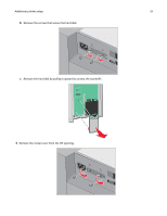 33
33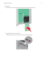 34
34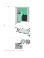 35
35 36
36 37
37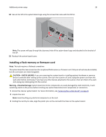 38
38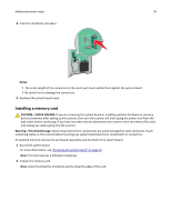 39
39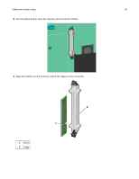 40
40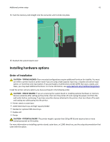 41
41 42
42 43
43