Makita LS0714 Owners Manual - Page 11
Operation - 7 1 2 accessories
 |
View all Makita LS0714 manuals
Add to My Manuals
Save this manual to your list of manuals |
Page 11 highlights
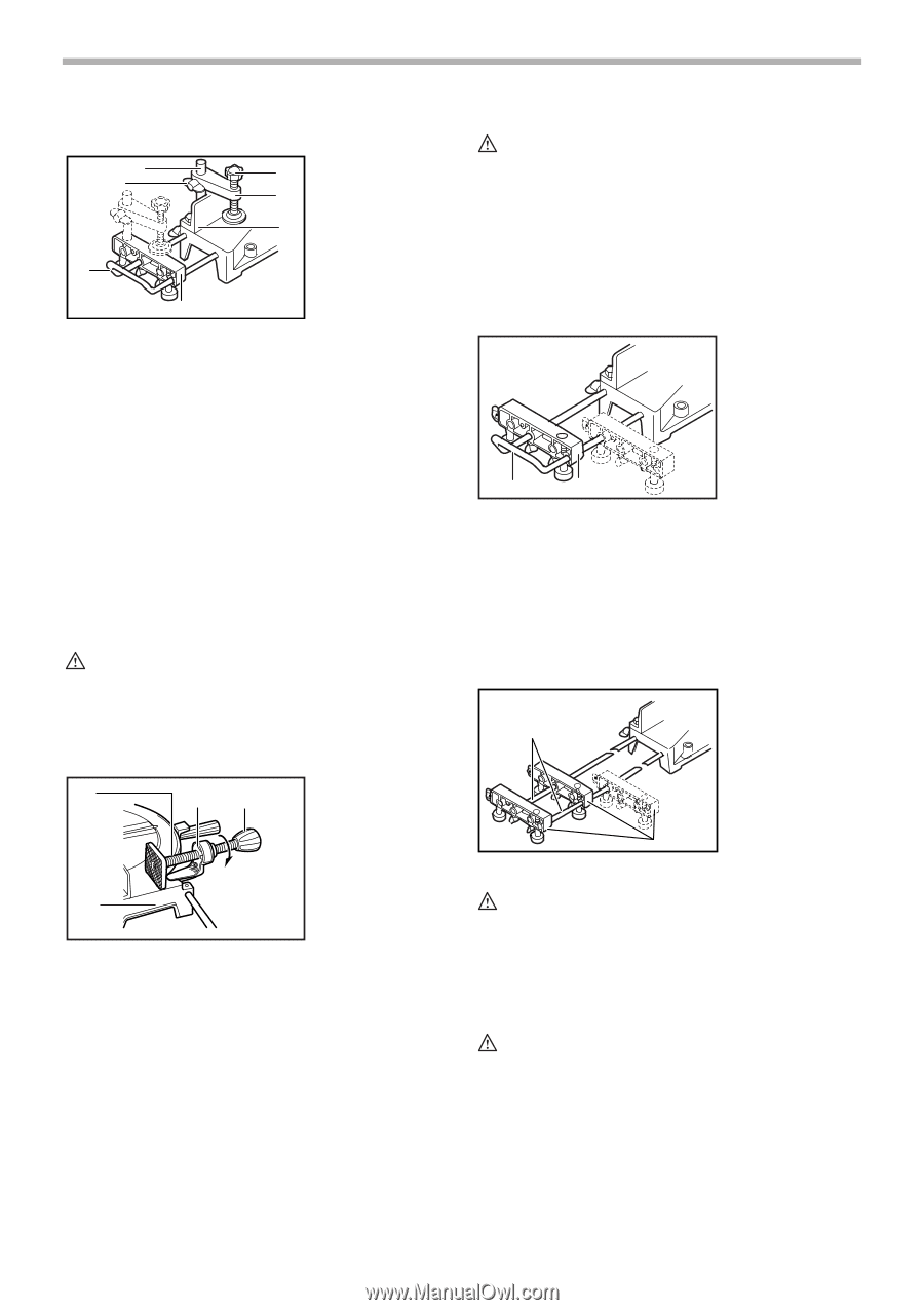
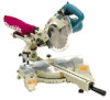
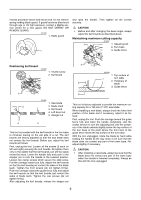
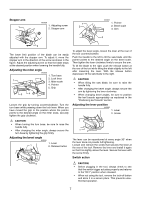
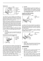
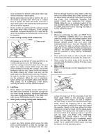
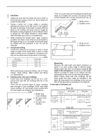
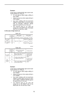
Vertical vise 2 7 4 5 002255 6 1. Vise arm 1 2. Vise rod 3. Guide fence 3 4. Holder 5. Holder assem- bly 6. Vise knob 7. Screw The vertical vise can be installed in two positions on either the left or right side of the guide fence or the holder assembly (optional accessory). Insert the vise rod into the hole in the guide fence or the holder assembly and tighten the screw to secure the vise rod. Position the vise arm according to the thickness and shape of the workpiece and secure the vise arm by tightening the screw. If the screw to secure the vise arm contacts the guide fence, install the screw on the opposite side of vise arm. Make sure that no part of the tool contacts the vise when lowering the handle fully and pulling or pushing the carriage all the way. If some part contacts the vise, re-position the vise. Press the workpiece flat against the guide fence and the turn base. Position the workpiece at the desired cutting position and secure it firmly by tightening the vise knob. CAUTION: • The workpiece must be secured firmly against the turn base and guide fence with the vise during all operations. Horizontal vise (optional accessory) 001807 3 21 1. Vise knob 2. Projection 3. Vise shaft 4. Base CAUTION: • Grip the workpiece only when the projection is at the topmost position. Failure to do so may result in insufficient securing of the workpiece. This could cause the workpiece to be thrown, cause damage to the blade or cause the loss of control, which can result in PERSONAL INJURY. Holders and holder assembly (optional accessories) 002247 1. Holder 2. Holder assem- bly 1 2 The holders and the holder assembly can be installed on either side as a convenient means of supporting workpieces horizontally. Install them as shown in the figure. Then tighten the screws firmly to secure the holders and the holder assembly. When cutting long workpieces, use the holder-rod assembly (optional accessory). It consists of two holder assemblies and two rods 12. 002246 1. Holder assem- 2 bly 2. Rod 12 1 4 The horizontal vise can be installed on the left side of the base. By turning the vise knob counterclockwise, the screw is released and the vise shaft can be moved rapidly in and out. By turning the vise knob clockwise, the screw remains secured. To grip the workpiece, turn the vise knob gently clockwise until the projection reaches its topmost position, then fasten securely. If the vise knob is forced in or pulled out while being turned clockwise, the projection may stop at an angle. In this case, turn the vise knob back counterclockwise until the screw is released, before turning again gently clockwise. The maximum width of the workpiece which can be secured by the horizontal vise is 120 mm (4-3/4"). CAUTION: • Always support long workpieces level with the top surface of the turn base for accurate cuts and to prevent dangerous loss of control of the tool. OPERATION CAUTION: • Before use, be sure to release the handle from the lowered position by pulling the stopper pin. • Make sure the blade is not contacting the work- piece, etc. before the switch is turned on. • Do not apply excessive pressure on the handle when cutting. Too much force may result in overload of the motor and/or decreased cutting efficiency. Push down handle with only as much force 11
-
 1
1 -
2
-
3
-
4
-
5
-
 6
6 -
 7
7 -
 8
8 -
 9
9 -
 10
10 -
 11
11 -
 12
12 -
 13
13 -
 14
14 -
 15
15 -
 16
16 -
17
-
18
-
19
-
20
-
21
-
22
-
23
-
24
-
25
-
26
-
27
-
28
-
29
-
30
-
31
-
32
-
33
-
34
-
35
-
36
-
37
-
38
-
39
-
40
-
41
-
42
-
43
-
44
-
45
-
46
-
47
-
48
-
49
-
50
-
51
-
52
-
53
-
54
-
55
-
56
-
57
-
58
-
59
-
60
-
61
-
62
-
63
-
64
-
65
-
66
-
67
-
68
 |
 |