Makita LS0714 Owners Manual - Page 13
CAUTION, Compound cutting, Cutting crown and cove moldings, Measuring, at the, back of the workpiece - sliding compound
 |
View all Makita LS0714 manuals
Add to My Manuals
Save this manual to your list of manuals |
Page 13 highlights
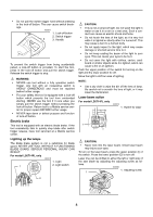
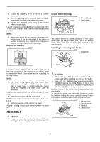
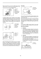
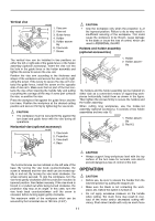
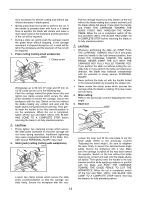
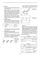
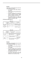
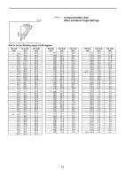
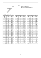
CAUTION: • Always be sure that the blade will move down to bevel direction during a bevel cut. Keep hands out of path of saw blade. • During a bevel cut, it may create a condition whereby the piece cut off will come to rest against the side of the blade. If the blade is raised while the blade is still rotating, this piece may be caught by the blade, causing fragments to be scattered which is dangerous. The blade should be raised ONLY after the blade has come to a complete stop. • When pressing the handle down, apply pressure parallel to the blade. If the pressure is not parallel to the blade during a cut, the angle of the blade might be shifted and the precision of the cut will be impaired. 5. Compound cutting Compound cutting is the process in which a bevel angle is made at the same time in which a miter angle is being cut on a workpiece. Compound cutting can be performed at angle shown in the table. 006393 Miter angle Left and Right 45˚ Right 50˚ Right 55˚ Right 57˚ Bevel angle Left 0˚ - 45˚ Left 0˚ - 40˚ Left 0˚ - 30˚ Left 0˚ - 25˚ When performing compound cutting, refer to "Press cutting", "Slide cutting", "Miter cutting" and "Bevel cut" explanations. 6. Cutting crown and cove moldings Crown and cove moldings can be cut on a compound miter saw with the moldings laid flat on the turn base. There are two common types of crown moldings and one type of cove moldings; 52/38° wall angle crown molding, 45° wall angle crown molding and 45° wall angle cove molding. See illustrations. 001555 1. 52/38° type crown molding 2. 45° type crown 52˚ 45˚ 45˚ molding 38˚ 45˚ 45˚ 3. 45° type cove molding 1 2 3 There are crown and cove molding joints which are made to fit "Inside" 90° corners ((1) and (2) in Fig. A) and "Outside" 90° corners ((3) and (4) in Fig. A). 001556 1. Inside corner 2. Outside corner Fig.A (1) (2) (3) (4) 1 2 001557 1. Inside corner 1 (2) (1) 2. Outside corner (1) (2) (4) (2) (3) 2 (1) (2) (1) (1) (2) Measuring Measure the wall length and adjust workpiece on table to cut wall contact edge to desired length. Always make sure that cut workpiece length at the back of the workpiece is the same as wall length. Adjust cut length for angle of cut. Always use several pieces for test cuts to check the saw angles. When cutting crown and cove moldings, set the bevel angle and miter angle as indicated in the table (A) and position the moldings on the top surface of the saw base as indicated in the table (B). In the case of left bevel cut Table (A) 006361 Molding Bevel angle position in Fig. A 52/38˚ type 45˚ type Miter angle 52/38˚ type 45˚ type For inside (1) corner (2) For outside (3) corner (4) Left 33.9˚ Left 30˚ Right 31.6˚ Right 35.3˚ Left 31.6˚ Left 35.3˚ Right 31.6˚ Right 35.3˚ Table (B) 006362 Molding position in Fig. A Molding edge against guide fence Finished piece For inside corner For outside corner (1) Ceiling contact edge should Finished piece be against guide fence. will be on the Left side of (2) Wall contact edge should be blade. against guide fence. (3) Finished piece will be on the Ceiling contact edge should Right side of (4) be against guide fence. blade. 13
-
 1
1 -
2
-
3
-
4
-
5
-
6
-
7
-
 8
8 -
 9
9 -
 10
10 -
 11
11 -
 12
12 -
 13
13 -
 14
14 -
 15
15 -
 16
16 -
 17
17 -
 18
18 -
19
-
20
-
21
-
22
-
23
-
24
-
25
-
26
-
27
-
28
-
29
-
30
-
31
-
32
-
33
-
34
-
35
-
36
-
37
-
38
-
39
-
40
-
41
-
42
-
43
-
44
-
45
-
46
-
47
-
48
-
49
-
50
-
51
-
52
-
53
-
54
-
55
-
56
-
57
-
58
-
59
-
60
-
61
-
62
-
63
-
64
-
65
-
66
-
67
-
68
 |
 |
