Netgear FS728TPv1 FS728TP User Manual - Page 155
Server, UDP Port, Facility, Description, Minimum Severity, Server IP
 |
View all Netgear FS728TPv1 manuals
Add to My Manuals
Save this manual to your list of manuals |
Page 155 highlights
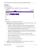
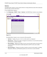
FS728TP Smart Switch FS728TP Smart Switch Software Administration Manual The Server Log screen contains the following fields: • Server IP - Enter the server's IP address to which logs can be sent. • UDP Port - Enter the UDP port to which the server logs are sent. The possible range is 1 - 65535. The default value is 514. • Facility - Select an application from which system logs are sent to the remote server. Only one facility can be assigned to a single server. If a second facility level is assigned, the first facility is overridden. All applications defined for a device utilize the same facility on a server. The field default is Local 0. The possible field values are Local 0 - Local 7. • Description - Enter a user-defined server description. • Minimum Severity - Select the minimum severity level for which logs are sent to the server. For example, if Notice is selected, all logs with a severity level of Notice and higher are sent to the remote server. The default value is Informational. The possible field values are: - Emergency - The highest warning level. If the device is down or not functioning properly, an emergency log message is saved to the specified logging location. - Alert - The second highest warning level. An alert log is saved, if there is a serious device malfunction; for example, all device features are down. - Critical - The third highest warning level. A critical log is saved if a critical device malfunction occurs; for example, two device ports are not functioning, while the rest of the device ports remain functional. - Error - A device error has occurred; for example, if a single port is offline. - Warning - The lowest level of a device warning. The device is functioning, but an operational problem has occurred. - Notice - Provides device information. - Informational - Provides device information. - Debug - Provides debugging messages. 2. Select the server entry. 3. Enter the Server IP address in the provided field in the first row. 4. Enter the UDP Port number in the provided field in the first row. 5. Select the Facility assigned to the server from the list in the provided field in the first row. 6. Enter an optional server Description in the provided field in the first row. 7-8 Monitoring the Switch v1.0, December 2007
-
 1
1 -
2
-
3
-
4
-
5
-
6
-
7
-
8
-
9
-
10
-
11
-
12
-
13
-
14
-
15
-
16
-
17
-
18
-
19
-
20
-
21
-
22
-
23
-
24
-
25
-
26
-
27
-
28
-
29
-
30
-
31
-
32
-
33
-
34
-
35
-
36
-
37
-
38
-
39
-
40
-
41
-
42
-
43
-
44
-
45
-
46
-
47
-
48
-
49
-
50
-
51
-
52
-
53
-
54
-
55
-
56
-
57
-
58
-
59
-
60
-
61
-
62
-
63
-
64
-
65
-
66
-
67
-
68
-
69
-
70
-
71
-
72
-
73
-
74
-
75
-
76
-
77
-
78
-
79
-
80
-
81
-
82
-
83
-
84
-
85
-
86
-
87
-
88
-
89
-
90
-
91
-
92
-
93
-
94
-
95
-
96
-
97
-
98
-
99
-
100
-
101
-
102
-
103
-
104
-
105
-
106
-
107
-
108
-
109
-
110
-
111
-
112
-
113
-
114
-
115
-
116
-
117
-
118
-
119
-
120
-
121
-
122
-
123
-
124
-
125
-
126
-
127
-
128
-
129
-
130
-
131
-
132
-
133
-
134
-
135
-
136
-
137
-
138
-
139
-
140
-
141
-
142
-
143
-
144
-
145
-
146
-
147
-
148
-
149
-
 150
150 -
 151
151 -
 152
152 -
 153
153 -
 154
154 -
 155
155 -
 156
156 -
 157
157 -
 158
158 -
 159
159 -
 160
160 -
161
-
162
-
163
-
164
-
165
-
166
-
167
-
168
-
169
-
170
-
171
-
172
-
173
-
174
-
175
-
176
-
177
-
178
-
179
-
180
-
181
-
182
-
183
-
184
-
185
 |
 |