Netgear RN3138 Rackmount Hardware Manual - Page 28
Front Panel, Health LED
 |
View all Netgear RN3138 manuals
Add to My Manuals
Save this manual to your list of manuals |
Page 28 highlights
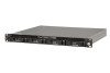
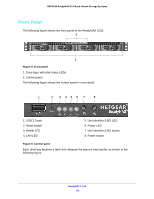
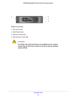
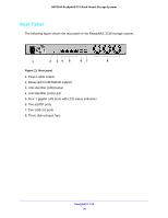
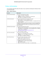
NETGEAR ReadyNAS OS 6 Rack-Mount Storage Systems Front Panel The following figure shows the front panel of the ReadyNAS 3138. 2 1 Figure 8. Front panel 1. Drive bays with disk status LEDs 2. Control panel The following figure shows the control panel in more detail. 1 2 3 45 6 7 8 1. USB 2.0 port 2. Reset button 3. Health LED 4. LAN LED 5. Unit identifier (UID) LED 6. Power LED 7. Unit identifier (UID) button 8. Power button Figure 9. Control panel Each drive bay features a latch that releases the pop-out tray handle, as shown in the following figure. ReadyNAS 3138 28
-
 1
1 -
2
-
3
-
4
-
5
-
6
-
7
-
8
-
9
-
10
-
11
-
12
-
13
-
14
-
15
-
16
-
17
-
18
-
19
-
20
-
21
-
22
-
 23
23 -
 24
24 -
 25
25 -
 26
26 -
 27
27 -
 28
28 -
 29
29 -
 30
30 -
 31
31 -
 32
32 -
 33
33 -
34
-
35
-
36
-
37
-
38
-
39
-
40
-
41
-
42
-
43
-
44
-
45
-
46
-
47
-
48
-
49
-
50
-
51
-
52
-
53
-
54
-
55
-
56
-
57
-
58
-
59
-
60
-
61
-
62
-
63
-
64
-
65
-
66
-
67
-
68
-
69
-
70
-
71
-
72
-
73
-
74
-
75
-
76
-
77
-
78
 |
 |

ReadyNAS 3138
28
NETGEAR ReadyNAS OS 6 Rack-Mount Storage Systems
Front Panel
The following figure shows the front panel of the ReadyNAS 3138.
2
1
Figure 8. Front panel
1. Drive bays with disk status LEDs
2. Control panel
The following figure shows the control panel in more detail.
5
6
7
1
2
3
4
8
Figure 9. Control panel
Each drive bay features a latch that releases the pop-out tray handle, as shown in the
following figure.
1. USB 2.0 port
2. Reset button
3. Health LED
4. LAN LED
5. Unit identifier (UID) LED
6. Power LED
7. Unit identifier (UID) button
8. Power button