Netgear RN3138 Rackmount Hardware Manual - Page 42
Table 4., Status indicators
 |
View all Netgear RN3138 manuals
Add to My Manuals
Save this manual to your list of manuals |
Page 42 highlights
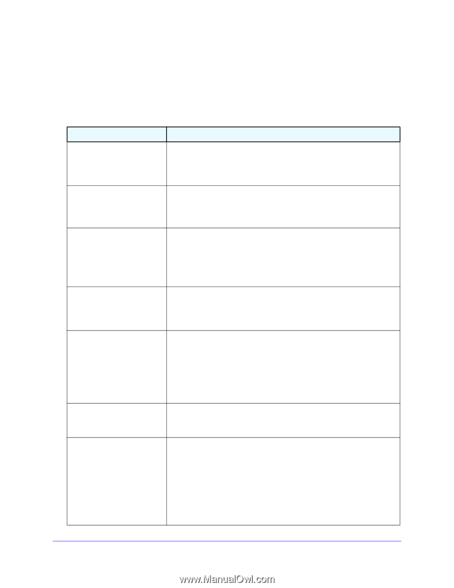
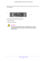
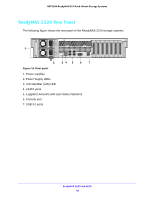
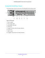
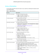
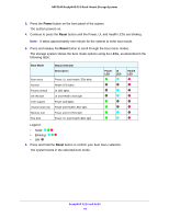
NETGEAR ReadyNAS OS 6 Rack-Mount Storage Systems Status Information You can obtain information about the status of your system by reviewing the indicators listed in the following table. Table 4. Status indicators Indicator Power LED (control panel) UI LED (control panel) Health LED (control panel) LAN LEDs (control panel) Disk LEDs (disk trays) UI LED (rear panel) LAN port LEDs (rear panel) Description The Power LED indicates these states: • Green. The system is powered on. • Amber. The system is in standby mode. • Off. The system is powered off. The UI LED indicates these states: • Blue. The system is identified: The UI button was pressed and the UID LED on the rear panel is lit. • Off. The system is not identified. The Health LED indicates these states: • Red. The system needs attention. Use the local admin page to determine the problem. For more information, see the ReadyNAS OS 6.4 Software Manual, which is available at http://support.netgear.com/product/ReadyNAS-OS6. • Off. The system is healthy. The LAN LEDs indicate these states: • Green. An Ethernet cable is connected. • Blinking. The Ethernet link is active. • Off. There is no Ethernet connection. The top LED indicates disk status, as follows: • On. A disk is present. • Off. No disk is present. The bottom LED indicates disk activity as follows: • Blinking. The disk is active. • Off. There is no disk activity. • Blinking on/off/on/off pattern. The disk failed or is faulty. The UI LED indicates these states: • On. The system is identified: The UI button was pressed. • Off. The system is not identified. Two LED status indicators are built into each LAN port. One LED is green and one is amber. They indicate port speed and activity as follows: • Green on, amber off. 1000 Mbps connection speed, no activity. • Green blinking, amber off. 1000 Mbps connection speed, activity. • Green off, amber on. 10 Mbps or 100 Mbps connection speed, no activity. • Green off, amber blinking. 10 Mbps or 100 Mbps connection speed, activity. • Green off, amber off. No connection. ReadyNAS 3220 and 4220 42
-
 1
1 -
2
-
3
-
4
-
5
-
6
-
7
-
8
-
9
-
10
-
11
-
12
-
13
-
14
-
15
-
16
-
17
-
18
-
19
-
20
-
21
-
22
-
23
-
24
-
25
-
26
-
27
-
28
-
29
-
30
-
31
-
32
-
33
-
34
-
35
-
36
-
 37
37 -
 38
38 -
 39
39 -
 40
40 -
 41
41 -
 42
42 -
 43
43 -
 44
44 -
 45
45 -
 46
46 -
 47
47 -
48
-
49
-
50
-
51
-
52
-
53
-
54
-
55
-
56
-
57
-
58
-
59
-
60
-
61
-
62
-
63
-
64
-
65
-
66
-
67
-
68
-
69
-
70
-
71
-
72
-
73
-
74
-
75
-
76
-
77
-
78
 |
 |