Onkyo TX-DS838 Owner Manual - Page 13
Connecting, video, equipment
 |
View all Onkyo TX-DS838 manuals
Add to My Manuals
Save this manual to your list of manuals |
Page 13 highlights
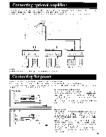
Connecting video equipment Refer to the instruction manual of each component when making connections. On each pair of connectors, the lower connector (red and marked R) corresponds to the right channel and the upper connector (white and marked L) to the left channel. TV/monitor Video cassette recorder (Video-2) DVD or TV (Video-3) 000 AUDIO IN VIDEO IN -r VIDEO IN AUDIO IN VIDEO IN (:)bO(.)(it 0,to 006660 6666001 u.c*' VIDEO OUT AUDIO OUT VIDEO OUT AUDIO OUT ANALOG VIDEO OUT AUDIO OUT ANALOG L VIDEO OUT AUDIO OUT DIGITAL OPTICAL OUT DIGITAL COAXIAL OUT A digital video disc player or other digital component equipped with an optical or coaxial connector can be connected to the TX-DS838. Do not disconnect the analog connection cable, even when one of these connectors are being used. If the analog cable is not connected, the multi-room system or headphones cannot be used. DIGITAL AC-3 RF OUT This connection can only be used to connect a VDP or other component equipped with an AC-3 RF output. Video cassette recorder (Video-1) If there should be interference between the TV and this unit, place this unit as far from the TV as possible. We do not recommend the use of a common TV/FM antenna. (Refer to Connecting antennas on page 19.) 000 Video cassette recorder (Video-4) Front panel ® 0 Oo VIDEO connector: Connect them when the video cam corder is provided with S-VIDEO connectors. VIDEO OUT 1 1 AUDIO OUT OOJ VIDEO-4/CAMCORDER There are VIDEO-4 INPUT connectors on both the front and rear panels. When a component is connected to the VIDEO-4/VIDEO CAM INPUT connector on the front panel, the component connected to the VIDEO-4 INPUT connector on the rear panel cannot be operated. When using a playback-only VCR, connect its output to the TXDS838's video input connector. NOTE: • When the video equipment is monaural, connect its audio output to the right (R) AUDIO input connector on this unit. • If a VDP's AC-3 RF output is connected to the TX-DS838's AC-3 RF DIGITAL INPUT connector, also connect the VDP's analog output to this unit's VIDEO-4 INPUT connectors. If a Dolby Digital (AC-3) laser disc is played back, the sound will automatically be reproduced in Dolby Digital (AC-3). 13
-
 1
1 -
2
-
3
-
4
-
5
-
6
-
7
-
 8
8 -
 9
9 -
 10
10 -
 11
11 -
 12
12 -
 13
13 -
 14
14 -
 15
15 -
 16
16 -
 17
17 -
 18
18 -
19
-
20
-
21
-
22
-
23
-
24
-
25
-
26
-
27
-
28
-
29
-
30
-
31
-
32
-
33
-
34
-
35
-
36
-
37
-
38
-
39
-
40
-
41
-
42
-
43
-
44
-
45
-
46
-
47
-
48
-
49
-
50
 |
 |
