Onkyo TX-DS838 Owner Manual - Page 20
above, steps, through, described, above
 |
View all Onkyo TX-DS838 manuals
Add to My Manuals
Save this manual to your list of manuals |
Page 20 highlights
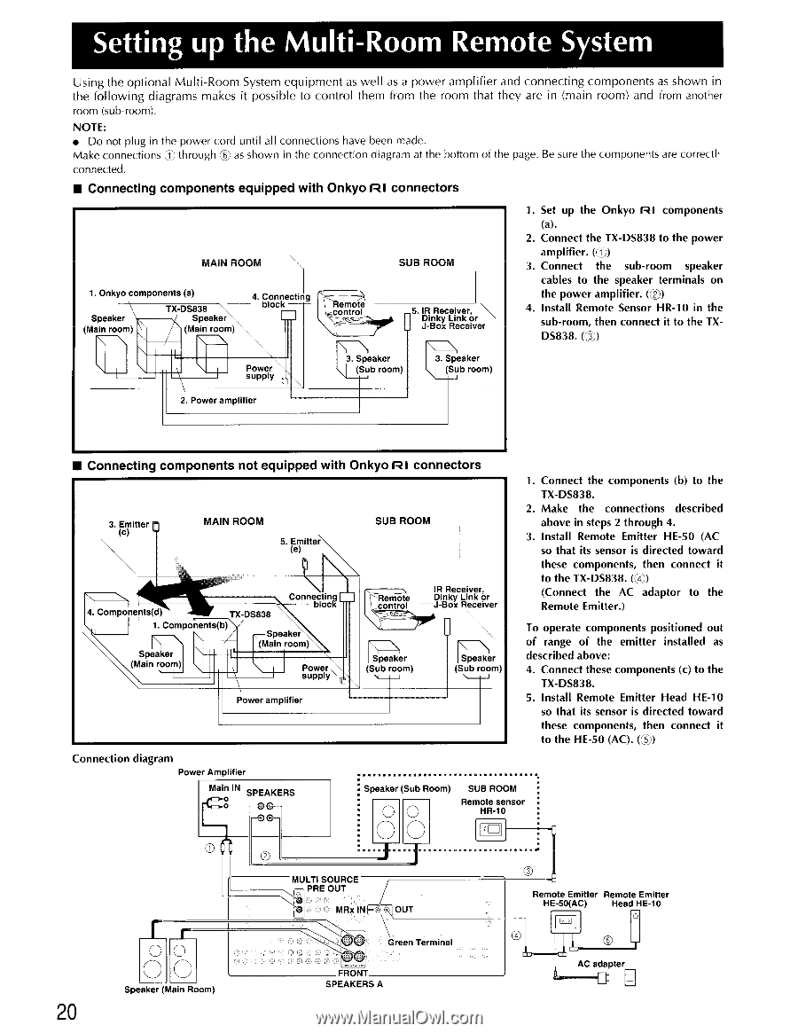
Setting up the Multi-Room Remote System Using the optional Multi-Room System equipment as well as a power amplifier and connecting components as shown in the following diagrams makes it possible to control them from the room that they are in (main room) and from another room (sub-room). NOTE: • Do not plug in the power cord until all connections have been made. Make connections Cji: through CO as shown in the connection diagram at the bottom of the page. Be sure the components are correctl' connected. • Connecting components equipped with Onkyo RI connectors MAIN ROOM 1. Onkyo components (a) Speaker (Main room) TX-DS838 Speaker (Main room) 4. Connecting block Remote control SUB ROOM _5. IR Receiver, Dinky Link or J-Box Receiver 1. Set up the Onkyo RI components (a). 2. Connect the TX-DS838 to the power amplifier. (4)) 3. Connect the sub-room speaker cables to the speaker terminals on the power amplifier. (I)) 4. Install Remote Sensor HR-10 in the sub-room, then connect it to the TXDS838. Power supply 3. Speaker \ (Sub room) 3. Speaker Sub room) 2. Power amplifier • Connecting components not equipped with Onkyo RI connectors 3. Emitter (c) MAIN ROOM 5. Emitter (e) SUB ROOM N 4. Components(d) TX-DS838 Connec ing block 1. Components(b) Speaker (Main room) Speaker (Main room) Power , supply Power amplifier Remote control IR Receiver, Dinky Link or J-Box Receiver Speaker (Sub room) Speaker (Sub room) N-J 1. Connect the components (b) to the TX-DS838. 2. Make the connections described above in steps 2 through 4. 3. Install Remote Emitter HE-50 (AC so that its sensor is directed toward these components, then connect it to the TX-DS838. (,4)) (Connect the AC adaptor to the Remote Emitter.) To operate components positioned out of range of the emitter installed as described above: 4. Connect these components (c) to the TX-DS838. 5. Install Remote Emitter Head HE-10 so that its sensor is directed toward these components, then connect it to the HE-50 (AC). (U) Connection diagram Power Amplifier Main IN SPEAKERS Speaker (Sub Room) 0 0 O O SUB ROOM Remote sensor HR-10 O 20 T T 0 r O O O Speaker (Main Room) O MULTI SOURCE PRE OUT IJ MRx INE--.)7R) OUT O. O Green Terminal FRONT SPEAKERS A O Remote Emitter Remote Emitter HE-50(AC) Head HE-10 AC adapter
-
 1
1 -
2
-
3
-
4
-
5
-
6
-
7
-
8
-
9
-
10
-
11
-
12
-
13
-
14
-
 15
15 -
 16
16 -
 17
17 -
 18
18 -
 19
19 -
 20
20 -
 21
21 -
 22
22 -
 23
23 -
 24
24 -
 25
25 -
26
-
27
-
28
-
29
-
30
-
31
-
32
-
33
-
34
-
35
-
36
-
37
-
38
-
39
-
40
-
41
-
42
-
43
-
44
-
45
-
46
-
47
-
48
-
49
-
50
 |
 |