Onkyo TX-DS838 Owner Manual - Page 21
Install, Connecting, Block, connect, TX-DS838., described, above
 |
View all Onkyo TX-DS838 manuals
Add to My Manuals
Save this manual to your list of manuals |
Page 21 highlights
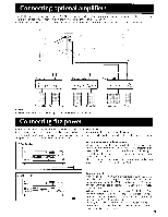
Setting up the Multi-Room Remote System AcIF !LULA I IRVAIU. .IILL:I- FICJII I Oyw.erri /I I n I V. J. Ctr IU lacUldUldl I II I(JU I ). NOTE: • Do not plug in the power cord until all connections have been made. Make connections 11 through 6 as shown in the connection diagram at the bottom of the page. Be sure the components are correctly connected. • Connecting components equipped with Onkyo RI connectors MAIN ROOM SUB ROOM 1. Onkyo components (a) Speaker (Main room) TX-DS838 Speaker (Main room) \ 4. Connecting block N \H_ Power supply 2. Power amplifier Remote control _5. Remote Sensor 3. Speaker \ (Sub room) 3. Speaker \ Sub room) 1. Set up the Onkyo RI components (a). 2. Connect the TX-DS838 to the power amplifier. (CD) 3. Connect the sub-room speaker cables to the speaker terminals on the power amplifier. (E2_;) 4. Install Connecting Block in the main room, then connect it to the TXDS838. 5. Install Xantech's J-Box Receiver or Dinky Link in the sub-room, then connect it to the Connecting Block in the main room. 01.;' ) ■ Connecting components not equipped with Onkyo RI connectors 3. Emitter (c) MAIN ROOM 5. Emitter (e) SUB ROOM 4. Components(d) TX-DS838 Connec ing block 1. Components(b) Speaker \ \ \ N Speaker (Main room) (Main roomN Power supply r. Power amplifier Remote control Speaker (Sub room) Remote Sensor Speaker (Sub room) N--1 1. Connect the components (b) to the TX-DS838. 2. Make the connections described above in steps 2 through 5. 3. Install Emitter (c) so that its sensor is directed toward the components, then connect it to the TX-DS838. (3_,) To operate components positioned out of range of the emitter installed as described above: 4. Connect these components (d) to the TX-DS838. 5. Install another Emitter (e) so that its sensor is directed toward these components, then connect it to the Connecting Block. (C6)) Connection diagram Power Amplifier Main o IN SPEAKERS o -3 Speaker (Sub Room) 0 0 Remote Sensor 0 SUB ROOM 0 0 00 Speaker (Main Room) MULTI SOURCE NI- PRE OUT L, MRx IN I-O``ouT ray Terminal FRONT SPEAKERS A Connecting block Emitter Power supply 21
-
 1
1 -
2
-
3
-
4
-
5
-
6
-
7
-
8
-
9
-
10
-
11
-
12
-
13
-
14
-
15
-
 16
16 -
 17
17 -
 18
18 -
 19
19 -
 20
20 -
 21
21 -
 22
22 -
 23
23 -
 24
24 -
 25
25 -
 26
26 -
27
-
28
-
29
-
30
-
31
-
32
-
33
-
34
-
35
-
36
-
37
-
38
-
39
-
40
-
41
-
42
-
43
-
44
-
45
-
46
-
47
-
48
-
49
-
50
 |
 |
