Panasonic 50LCX63 Multi-media Display - Page 37
Changing the input signal, TV/VIDEO, SD on the Remote
 |
View all Panasonic 50LCX63 manuals
Add to My Manuals
Save this manual to your list of manuals |
Page 37 highlights
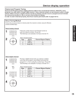
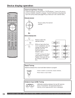
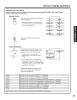
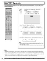
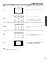
Device display operation Changing the input signal The input source for picture signals can be changed by pressing TV/VIDEO, SD on the Remote Control or CH up/down on the unit. Remote Control The input mode changes each time this button is pressed. TV HDMI* * If SKIP is set as the Input Label setting of Channel Caption, the mode will not be changed. (See page 69.) Video 1* Video 2* RGB 2* RGB 1* Video 3* Comp 3* Comp 1* Comp 2* Card input mode (Photo Viewer) is selected. Basic Operation Device display Unit By pressing Channel Up/Down buttons together, you can switch between TV mode and an outside input source. *1 Changing input is only possible if Cable/Antenna is set as the Input Set setting. *2 Input changes to the first outside input source of the Input Label not set to SKIP. For example, if Video 1 is set to SKIP, input is changed to Video 2. See the chart, below (except for Photo mode). TV Antenna A Antenna B*1 Video 1*2 While Photo Viewer is displayed, the channel or outside input source last viewed is redisplayed. Video 1 Video 2 Video 3 Comp 1 Comp 2 Comp 3 RGB 1 RGB 2 HDMI Signal of source connected to INPUT 1 is displayed. Signal of source connected to INPUT 2 is displayed. Signal of source connected to INPUT 3 is displayed. Signal of source connected to COMPONENT VIDEO INPUT 1 is displayed. Signal of source connected to COMPONENT VIDEO INPUT 2 is displayed. Signal of source connected to COMPONENT VIDEO INPUT 3 is displayed. Signal of source connected to RGB IN 1 is displayed. Signal of source connected to RGB IN 2 is displayed. Signal of source connected to HDMI IN is displayed. Photo (Photo Viewer) Signal of source connected to CARD SLOT is displayed. 37
-
 1
1 -
2
-
3
-
4
-
5
-
6
-
7
-
8
-
9
-
10
-
11
-
12
-
13
-
14
-
15
-
16
-
17
-
18
-
19
-
20
-
21
-
22
-
23
-
24
-
25
-
26
-
27
-
28
-
29
-
30
-
31
-
 32
32 -
 33
33 -
 34
34 -
 35
35 -
 36
36 -
 37
37 -
 38
38 -
 39
39 -
 40
40 -
 41
41 -
 42
42 -
43
-
44
-
45
-
46
-
47
-
48
-
49
-
50
-
51
-
52
-
53
-
54
-
55
-
56
-
57
-
58
-
59
-
60
-
61
-
62
-
63
-
64
-
65
-
66
-
67
-
68
-
69
-
70
-
71
-
72
-
73
-
74
-
75
-
76
-
77
-
78
-
79
-
80
-
81
-
82
-
83
-
84
-
85
-
86
-
87
-
88
-
89
-
90
-
91
-
92
-
93
-
94
-
95
-
96
-
97
-
98
-
99
-
100
-
101
-
102
-
103
-
104
-
105
-
106
-
107
-
108
 |
 |
