Panasonic VDRM55PP Dvd Video Camera-oem - Page 19
Names Of Parts - vdrm53pp
 |
View all Panasonic VDRM55PP manuals
Add to My Manuals
Save this manual to your list of manuals |
Page 19 highlights
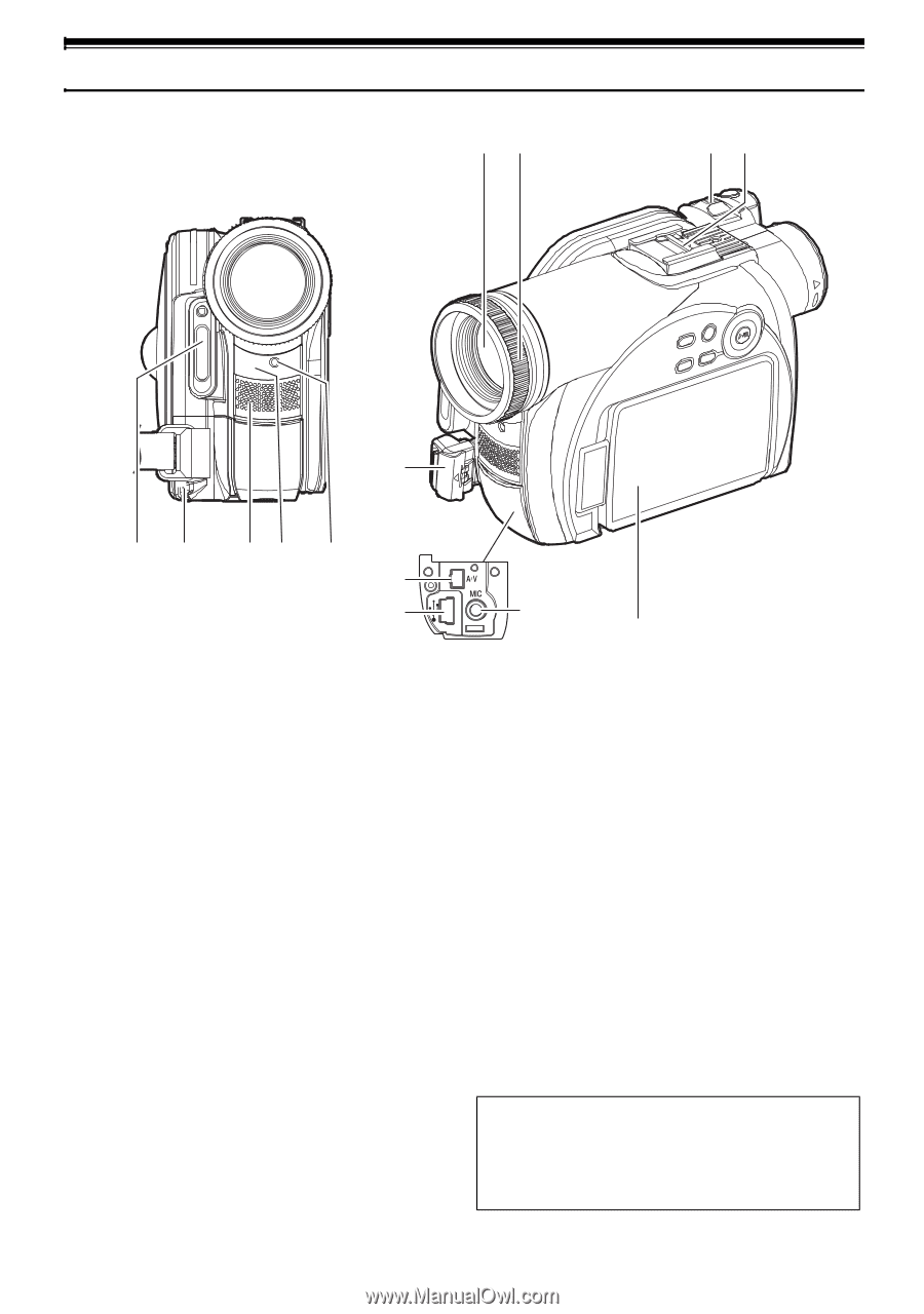
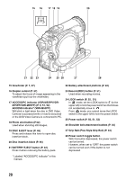
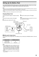
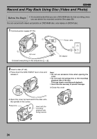
Names of Parts 67 89 10 12 34 5 12 11 13 14 (Inside the cover) 1 Built-in flash (VDR-M95PP) (P.68) There is a sensor at the top of the flash. 2 Lens cap string attachment hole (P. 35) 3 Internal stereo microphone (P. 51) 8 Zoom lever (P. 57) Push the lever to the T side for telephoto, or to the W side for wide-angle. 9 Accessory shoe (P. 69) Attach the optional flash. 4 Infrared receiver (VDR-M55PP/VDR-M75PP/ VDR-M95PP) (P. 37) When the remote controller is used to operate the DVD Video Camera, this receiver will receive the infrared signal. 5 Recording indicator (P. 94) The red indicator will light during recording. 10 Lock cover and Lock button (P. 34) 11 USB port (VDR-M55PP/VDR-M75PP/VDR- M95PP) (P.13) 12 AV input/output jack (P. 71, 75, 77) 13 External microphone jack (P. 70) 6 Optical 10x zoom lens (VDR-M75PP/VDRM95PP) Optical 24× zoom lens (VDR-M53PP/VDRM55PP) (P. 57) 7 Lens hood 14 2.5" type Liquid Crystal Display (LCD) (inside) (P. 7, 38) Although the external appearances of VDRM53PP, VDR-M55PP, VDR-M75PP and VDRM95PP are different, they are both operated in the same way. VDR-M95PP illustrations are used in this manual. 19
-
 1
1 -
2
-
3
-
4
-
5
-
6
-
7
-
8
-
9
-
10
-
11
-
12
-
13
-
 14
14 -
 15
15 -
 16
16 -
 17
17 -
 18
18 -
 19
19 -
 20
20 -
 21
21 -
 22
22 -
 23
23 -
 24
24 -
25
-
26
-
27
-
28
-
29
-
30
-
31
-
32
-
33
-
34
-
35
-
36
-
37
-
38
-
39
-
40
-
41
-
42
-
43
-
44
-
45
-
46
-
47
-
48
-
49
-
50
-
51
-
52
-
53
-
54
-
55
-
56
-
57
-
58
-
59
-
60
-
61
-
62
-
63
-
64
-
65
-
66
-
67
-
68
-
69
-
70
-
71
-
72
-
73
-
74
-
75
-
76
-
77
-
78
-
79
-
80
-
81
-
82
-
83
-
84
-
85
-
86
-
87
-
88
-
89
-
90
-
91
-
92
-
93
-
94
-
95
-
96
-
97
-
98
-
99
-
100
-
101
-
102
-
103
-
104
-
105
-
106
-
107
-
108
-
109
-
110
-
111
-
112
-
113
-
114
-
115
-
116
-
117
-
118
-
119
-
120
-
121
-
122
-
123
-
124
-
125
-
126
-
127
-
128
-
129
-
130
-
131
-
132
-
133
-
134
-
135
-
136
-
137
-
138
-
139
-
140
-
141
-
142
-
143
-
144
-
145
-
146
-
147
-
148
-
149
-
150
-
151
-
152
-
153
-
154
-
155
-
156
-
157
-
158
-
159
-
160
-
161
-
162
-
163
-
164
-
165
-
166
-
167
-
168
-
169
-
170
 |
 |