Panasonic WJHD316 WJHD309 User Guide - Page 73
Connections with the VTR
 |
View all Panasonic WJHD316 manuals
Add to My Manuals
Save this manual to your list of manuals |
Page 73 highlights
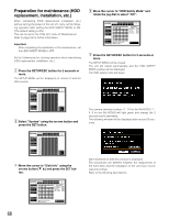
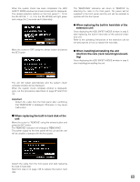
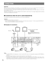
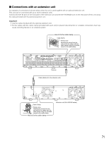
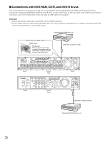
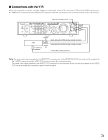
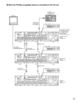
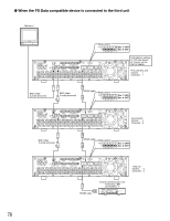
I Connections with the VTR When it is necessary to copy the recorded images to a video tape using a VTR, connect the VTR to the S-VIDEO connector (or the VIDEO OUT connector) and the AUDIO OUT connector inside the connectors cover on the front panel of this unit as below. Open the connectors cover. MONITOR1 MONITOR2 TIMER 123 4 STOP PLAY PAUSE REC - REC STOP REV FWD ALARM ERROR PAN/ GOTO TILT LAST SEARCH SHIFT SEQ OSD PAN/TILT SETUP ALARM SUSPEND ALARM RESET 567 8 DISK SELECT COPY TEXT MARK ZOOM/ FOCUS A-B SLOW REPEAT /ESC - + 9 10/0 11 12 IRIS LISTED OPERATE HDD 1 EL-ZOOM LOGOUT LOGOUT PRESET /AUTO HDD 2 13 14 15 16 SET BUSY S-VIDEO COPY 2 VIDEO OUT AUDIO OUT AUDIO IN VTR S-VIDEO IN connector VIDEO IN Audio cable with an RCA pin plug (Locally procured) Audio cable with an RCA pin plug (Locally procured) S-video cable (Locally procured) Note: The same video signal supplied to the MONITOR1 connector and to the MONITOR2 (VGA) connector will be supplied to the S-VIDEO connector and the VIDEO OUT connector inside the connectors cover. The same audio signal supplied to the AUDIO OUT connector on the rear panel of this unit will be supplied to the AUDIO OUT connector inside the connectors cover on the front panel. 73
-
 1
1 -
2
-
3
-
4
-
5
-
6
-
7
-
8
-
9
-
10
-
11
-
12
-
13
-
14
-
15
-
16
-
17
-
18
-
19
-
20
-
21
-
22
-
23
-
24
-
25
-
26
-
27
-
28
-
29
-
30
-
31
-
32
-
33
-
34
-
35
-
36
-
37
-
38
-
39
-
40
-
41
-
42
-
43
-
44
-
45
-
46
-
47
-
48
-
49
-
50
-
51
-
52
-
53
-
54
-
55
-
56
-
57
-
58
-
59
-
60
-
61
-
62
-
63
-
64
-
65
-
66
-
67
-
 68
68 -
 69
69 -
 70
70 -
 71
71 -
 72
72 -
 73
73 -
 74
74 -
 75
75 -
 76
76 -
 77
77 -
 78
78 -
79
-
80
-
81
-
82
-
83
-
84
-
85
-
86
-
87
-
88
-
89
-
90
-
91
-
92
-
93
-
94
-
95
-
96
-
97
-
98
-
99
-
100
-
101
-
102
-
103
-
104
-
105
-
106
-
107
-
108
-
109
-
110
-
111
-
112
-
113
-
114
-
115
-
116
-
117
-
118
-
119
-
120
-
121
-
122
-
123
-
124
-
125
-
126
-
127
-
128
-
129
-
130
-
131
-
132
-
133
-
134
-
135
-
136
-
137
-
138
-
139
-
140
-
141
-
142
-
143
-
144
-
145
-
146
-
147
-
148
-
149
-
150
-
151
-
152
-
153
-
154
-
155
-
156
-
157
-
158
-
159
-
160
-
161
-
162
-
163
-
164
 |
 |
