Panasonic WJHD316 WJHD309 User Guide - Page 89
How to Use the SERIAL Connector, Pin Configuration, Connection example
 |
View all Panasonic WJHD316 manuals
Add to My Manuals
Save this manual to your list of manuals |
Page 89 highlights
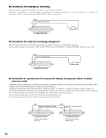
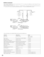
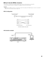
I How to Use the SERIAL Connector This connector is compliant with the RS232C Standard, and is used to communicate with a connected PC. A connection example and the pin configuration of the SERIAL connector are as shown below. Important: • When using the SERIAL connector, it is necessary to perform the settings with "RS232C Setup" of "Comm" on the SETUP MENU for the communication functions. (Page 118) G Pin Configuration Serial connector of this unit D-sub Pin 9 (Female) Personal computer side D-sub Pin 9 (Female) (Locally procured) 7 (RTS) 8 (CTS) 3 (TXD) 5 (GND) 2 (RXD) 7 (RTS) 8 (CTS) 3 (TXD) 5 (GND) 2 (RXD) WJ-HD316/WJ-HD309 PC or another device Connection example of cross cable G Connection example D-sub Pin 9 (Female) 3 1 1 SERIAL ALARM 4 2 AUDIO IN AUDIO OUT CASCADE OUT 2 MONITOR OUT CASCADE IN MONITOR (VGA) ALARM/CONTOROL 16 15 14 13 12 11 10 9 8 7 IN OUT 16 15 14 13 12 11 10 9 8 7 VIDEO MODE 2 1 COPY 1 DATA 6 5 RS485(CAMERA) 10/100BASE-T EXT STORAGE 4 3 2 1 6 5 4 3 2 1 This unit D-sub Pin 9 (Female) SIGNAL GND POWER AC IN PC 89
-
 1
1 -
2
-
3
-
4
-
5
-
6
-
7
-
8
-
9
-
10
-
11
-
12
-
13
-
14
-
15
-
16
-
17
-
18
-
19
-
20
-
21
-
22
-
23
-
24
-
25
-
26
-
27
-
28
-
29
-
30
-
31
-
32
-
33
-
34
-
35
-
36
-
37
-
38
-
39
-
40
-
41
-
42
-
43
-
44
-
45
-
46
-
47
-
48
-
49
-
50
-
51
-
52
-
53
-
54
-
55
-
56
-
57
-
58
-
59
-
60
-
61
-
62
-
63
-
64
-
65
-
66
-
67
-
68
-
69
-
70
-
71
-
72
-
73
-
74
-
75
-
76
-
77
-
78
-
79
-
80
-
81
-
82
-
83
-
 84
84 -
 85
85 -
 86
86 -
 87
87 -
 88
88 -
 89
89 -
 90
90 -
 91
91 -
 92
92 -
 93
93 -
 94
94 -
95
-
96
-
97
-
98
-
99
-
100
-
101
-
102
-
103
-
104
-
105
-
106
-
107
-
108
-
109
-
110
-
111
-
112
-
113
-
114
-
115
-
116
-
117
-
118
-
119
-
120
-
121
-
122
-
123
-
124
-
125
-
126
-
127
-
128
-
129
-
130
-
131
-
132
-
133
-
134
-
135
-
136
-
137
-
138
-
139
-
140
-
141
-
142
-
143
-
144
-
145
-
146
-
147
-
148
-
149
-
150
-
151
-
152
-
153
-
154
-
155
-
156
-
157
-
158
-
159
-
160
-
161
-
162
-
163
-
164
 |
 |
