Panasonic WJHD316 WJHD309 User Guide - Page 74
Connections with PS・Data systems, When connecting this unit with a controller
 |
View all Panasonic WJHD316 manuals
Add to My Manuals
Save this manual to your list of manuals |
Page 74 highlights
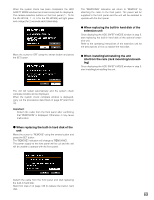
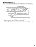
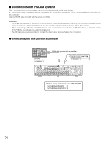
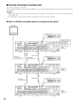
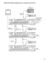
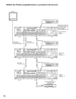
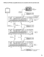
I Connections with PS·Data systems This is an example of connection when the unit is used together with the PS·Data devices. If a connected system controller is PS·Data compatible, it is possible to operate this unit or connected devices using the system controller. Use the RS485 cable provided with the system controller. Important: • Terminate both devices on both ends of the connection. Refer to the respective operating instructions for the descriptions of how to terminate. Termination of this unit can be set with the mode switch on the rear panel. (See below.) • When connecting a PS·Data compatible device, it is necessary to set each item of "PS·Data Setup" of "Comm" on the SETUP MENU according to the system configuration. • The PS·Data is our exclusive protocol. Contact the dealer about devices that can be connected. G When connecting this unit with a controller System Controller Controller Termination: ON Unit Address : 1 RS485 cable (provided with the controller) Mode switch ON 12345678 (No. 7: ON) (No. 8: OFF) 3 1 1 SERIAL ALARM 4 2 AUDIO IN AUDIO OUT CASCADE OUT 2 MONITOR OUT CASCADE IN MONITOR (VGA) ALARM/CONTOROL 16 15 14 13 12 11 10 9 8 7 IN OUT 16 15 14 13 12 11 10 9 8 7 VIDEO MODE 2 1 COPY 1 DATA 6 5 RS485(CAMERA) 10/100BASE-T EXT STORAGE 4 3 2 1 6 5 4 3 2 1 SIGNAL GND POWER AC IN "PS·Data setup" of "Comm" on the SETUP MENU • Unit Address (System) : 1 • Unit Address (Controller) : 2 74
-
 1
1 -
2
-
3
-
4
-
5
-
6
-
7
-
8
-
9
-
10
-
11
-
12
-
13
-
14
-
15
-
16
-
17
-
18
-
19
-
20
-
21
-
22
-
23
-
24
-
25
-
26
-
27
-
28
-
29
-
30
-
31
-
32
-
33
-
34
-
35
-
36
-
37
-
38
-
39
-
40
-
41
-
42
-
43
-
44
-
45
-
46
-
47
-
48
-
49
-
50
-
51
-
52
-
53
-
54
-
55
-
56
-
57
-
58
-
59
-
60
-
61
-
62
-
63
-
64
-
65
-
66
-
67
-
68
-
 69
69 -
 70
70 -
 71
71 -
 72
72 -
 73
73 -
 74
74 -
 75
75 -
 76
76 -
 77
77 -
 78
78 -
 79
79 -
80
-
81
-
82
-
83
-
84
-
85
-
86
-
87
-
88
-
89
-
90
-
91
-
92
-
93
-
94
-
95
-
96
-
97
-
98
-
99
-
100
-
101
-
102
-
103
-
104
-
105
-
106
-
107
-
108
-
109
-
110
-
111
-
112
-
113
-
114
-
115
-
116
-
117
-
118
-
119
-
120
-
121
-
122
-
123
-
124
-
125
-
126
-
127
-
128
-
129
-
130
-
131
-
132
-
133
-
134
-
135
-
136
-
137
-
138
-
139
-
140
-
141
-
142
-
143
-
144
-
145
-
146
-
147
-
148
-
149
-
150
-
151
-
152
-
153
-
154
-
155
-
156
-
157
-
158
-
159
-
160
-
161
-
162
-
163
-
164
 |
 |
