Pentair WaterFall Specialty Pumps WaterFall Owners Manual English Spanish Fren - Page 3
The Virginia Graeme Baker VGB Pool and Spa Safety Act
 |
View all Pentair WaterFall Specialty Pumps manuals
Add to My Manuals
Save this manual to your list of manuals |
Page 3 highlights
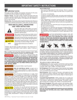
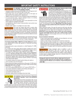
ENGLISH ESPAÑOL FRANÇAIS ii IMPORTANT SAFETY INSTRUCTIONS TO MINIMIZE THE RISK OF INJURY DUE TO SUCTION ENTRAPMENT HAZARD: • A properly installed and secured ANSI/ASME A112.19.8 approved antientrapment suction cover must be used for each drain. • Each suction cover must be installed at least three (3') feet apart, as measured from the nearest point to nearest point. • Regularly inspect all covers for cracks, damage and advanced weathering. • If a cover becomes loose, cracked, damaged, broken or is missing, replace with an appropriate certified cover. • Replace drain covers as necessary. Drain covers deteriorate over time due to exposure to sunlight and weather. • Avoid getting hair, limbs or body in close proximity to any suction cover, pool drain or outlet. • Disable suction outlets or reconfigure into return inlets. The pump can produce high levels of suction within the suction side of the plumbing system. These high levels of suction can pose a risk if a person comes within the close proximity of the suction openings. A person can be seriously injured by this high level of vacuum or may become trapped and drown. It is absolutely critical that the suction plumbing be installed in accordance with the latest national and local codes for swimming pools. A clearly labeled emergency shut-off switch for the pump must be in an easily accessible, obvious place. Make sure users know where it is and how to use it in case of emergency. The Virginia Graeme Baker (VGB) Pool and Spa Safety Act creates new requirements for owners and operators of commercial swimming pools and spas. Commercial pools or spas constructed on or after December 19, 2008, shall utilize: (A) A multiple main drain system without isolation capability with suction outlet covers that meet ASME/ANSI A112.19.8a Suction Fittings for Use in Swimming Pools, Wading Pools, Spas, and Hot Tubs and either: (i) A safety vacuum release system (SVRS) meeting ASME/ANSI A112.19.17 Manufactured Safety Vacuum Release systems (SVRS) for Residential and Commercial Swimming Pool, Spa, Hot Tub, and Wading Pool Suction Systems and/or ASTM F2387 Standard Specification for Manufactured Safety Vacuum Release Systems (SVRS) for Swimming pools, Spas and Hot Tubs or (ii) A properly designed and tested suction-limiting vent system or (iii) An automatic pump shut-off system. Commercial pools and spas constructed prior to December 19, 2008, with a single submerged suction outlet shall use a suction outlet cover that meets ASME/ANSI A112.19.8a and either: (A) A SVRS meeting ASME/ANSI A112.19.17 and/or ASTM F2387, or (B) A properly designed and tested suction-limiting vent system, or (C) An automatic pump shut-off system, or (D) Disabled submerged outlets, or (E) Suction outlets shall be reconfigured into return inlets. HAZARDOUS PRESSURE: STAND CLEAR OF PUMP AND FILTER DURING START UP. Circulation systems operate under high pressure. When any part of the circulating system (i.e. locking ring, pump, filter, valves, etc.) is serviced, air can enter the system and become pressurized. Pressurized air can cause the pump housing cover, filter lid, and valves to violently separate which can result in severe personal injury or death. Filter tank lid and strainer cover must be properly secured to prevent violent separation. Stand clear of all circulation system equipment when turning on or starting up pump. Before servicing equipment, make note of the filter pressure. Be sure that all controls are set to ensure the system cannot inadvertently start during service. Turn off all power to the pump. IMPORTANT: Place filter manual air relief valve in the open position and wait for all pressure in the system to be relieved. Before starting the system, fully open the manual air relief valve and place all system valves in the "open" position to allow water to flow freely from the tank and back to the tank. Stand clear of all equipment and start the pump. IMPORTANT: Do not close filter manual air relief valve until all pressure has been discharged from the valve and a steady stream of water appears. Observe filter pressure gauge and be sure it is not higher than the pre-service condition. General Installation Information • All work must be performed by a qualified service professional, and must conform to all national, state, and local codes. • Install to provide drainage of compartment for electrical components. • These instructions contain information for a variety of pump models and therefore some instructions may not apply to a specific model. All models are intended for use in swimming pool applications. The pump will function correctly only if it is properly sized to the specific application and properly installed. Pumps improperly sized or installed or used in applications other than for which the pump was intended can result in severe personal injury or death. These risks may include but not be limited to electric shock, fire, flooding, suction entrapment or severe injury or property damage caused by a structural failure of the pump or other system component. Pumps and replacement motors that are single speed and one (1) Total HP or greater cannot be sold, offered for sale, or installed in a residential pool for filtration use in California, Title 20 CCR sections 1601-1609. For Installation of Electrical Controls at Equipment Pad (ON/OFF Switches, Timers and Automation Load Center) Install all electrical controls at equipment pad, such as on/off switches, timers, and control systems, etc. to allow the operation (startup, shut-down, or servicing) of any pump or filter so the user does not place any portion of his/her body over or near the pump strainer lid, filter lid or valve closures. This installation should allow the user enough space to stand clear of the filter and pump during system start-up, shut down or servicing of the system filter. Warning Page P/N 352557 Rev. D 11/19 WATERFALL™ Specialty Pump Installation and User's Guide
-
 1
1 -
 2
2 -
 3
3 -
 4
4 -
 5
5 -
 6
6 -
 7
7 -
 8
8 -
 9
9 -
10
-
11
-
12
-
13
-
14
-
15
-
16
-
17
-
18
-
19
-
20
-
21
-
22
-
23
-
24
-
25
-
26
-
27
-
28
-
29
-
30
-
31
-
32
-
33
-
34
-
35
-
36
-
37
-
38
-
39
-
40
-
41
-
42
-
43
-
44
-
45
-
46
-
47
-
48
-
49
-
50
-
51
-
52
-
53
-
54
-
55
-
56
 |
 |
