Philips DVDR3355 User manual - Page 18
Connecting to a VCR and, Cable Box/Satellite Receiver
 |
View all Philips DVDR3355 manuals
Add to My Manuals
Save this manual to your list of manuals |
Page 18 highlights
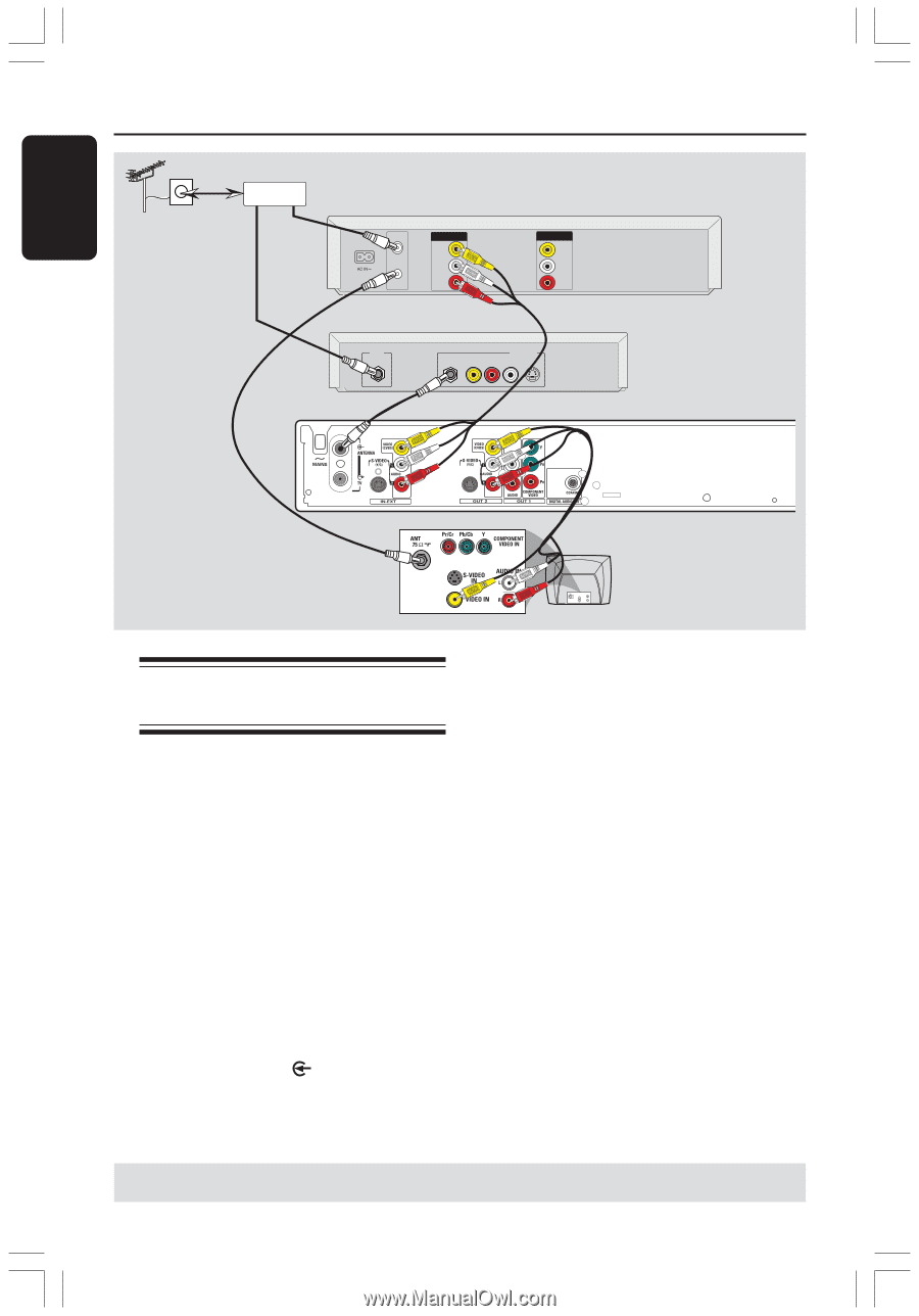
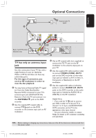
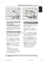
English Optional Connections (continued) Antenna/cable TV signals SPLITTER 1 VHF/UHF RF IN VHF/UHF RF OUT IN 3 Back of aVCR (Example only) OUT VIDEO OUT AUDIO L AUDIO R IN VIDEO IN AUDIO L AUDIO R 4 OUT RF VIDEO AUDIO R L S-VIDEO Back of a Cable Box or Satellite Receiver (Example only) 2 5 TV AU D IO O UT S-V ID E O IN V ID E O IN Connecting to a VCR and Cable Box/Satellite Receiver A splitter (not supplied) is required for this connection. 1 Connect the Antenna/Cable TV signal to a splitter. Then connect the RF coaxial cables from the splitter to the antenna input (RF IN) jack on the VCR and the Cable Box/Satellite Receiver. 2 Use an RF coaxial cable to connect the antenna output (RF OUT) jack on the VCR to the antenna input jack on the TV. 3 Use the supplied RF coaxial cable to connect the antenna output (RF OUT) jack on the Cable Box/Satellite Receiver to the ANTENNA jack on the DVD recorder. 4 Use the audio/video cables to connect VIDEO/AUDIO IN-EXT on the DVD recorder to the matching VIDEO/AUDIO output jacks on the VCR. 5 Use the audio/video cables to connect VIDEO/AUDIO OUT-2 on the DVD recorder to the matching VIDEO/AUDIO input jacks on the TV. Helpful Hints: - You may use the S-VIDEO (Y/C) jack instead of VIDEO (CVBS) jack if the connected device has the same S-VIDEO input/output jack. This video connection provides better picture quality. TIPS: Before making or changing any connections, make sure that all the devices are disconnected from the power outlet. 18 001_033_dvdr3355_37A_eng5 18 21/3/05, 3:16 PM
-
 1
1 -
2
-
3
-
4
-
5
-
6
-
7
-
8
-
9
-
10
-
11
-
12
-
 13
13 -
 14
14 -
 15
15 -
 16
16 -
 17
17 -
 18
18 -
 19
19 -
 20
20 -
 21
21 -
 22
22 -
 23
23 -
24
-
25
-
26
-
27
-
28
-
29
-
30
-
31
-
32
-
33
-
34
-
35
-
36
-
37
-
38
-
39
-
40
-
41
-
42
-
43
-
44
-
45
-
46
-
47
-
48
-
49
-
50
-
51
-
52
-
53
-
54
-
55
-
56
-
57
-
58
-
59
-
60
 |
 |