| Section |
Page |
| FEATURES |
5 |
| This unit is a multi entertainment player designed with a wide array of performance functions for parties and events, together w... |
5 |
| With the normal playing style, DJ play can be performed not only with conventional music CDs (CD-DA), but also with music files ... |
5 |
| Also, by connecting this player to a computer equipped with the accessory DJS software, this player can be designated by DJS as ... |
5 |
| The player also features excellent media-support characteristics, making it unnecessary to worry about specific media types, and... |
5 |
| On the other hand, the control unit continues the tradition of Pioneer’s CDJ series of players in its panel layout, functions an... |
5 |
| . A dedicated ASIO driver is also available for audio output. |
7 |
| SPECIFICATIONS |
9 |
| 1 General |
9 |
| 2 USB Upstream Section |
9 |
| USB Downstream Section |
9 |
| 3 Analog Audio Output Section |
9 |
| 4 Digital Audio Output Section |
9 |
| 5 Video Output Section |
9 |
| 6 Center Display Section |
9 |
| 7 Controller Display A/B Section |
9 |
| 8 Other Connectors |
9 |
| COMFIRM ACCESSORIES |
10 |
| Confirm that all furnished accessories are present. |
10 |
| . MEP-7000 units marketed in China do not include the DJS software set. |
10 |
| . Three instruction manuals are furnished (including the one you are reading). Please study these manuals in accord with your manner of use: |
10 |
| - MEP-7000 Operating Instructions (this manual) |
10 |
| - MEP-7000 DJS Control Guide (PDF file recorded on accessory CD-ROM) |
10 |
| - DJS User’s Manual (PDF file recorded on accessory CD-ROM) |
10 |
| REGARDING PLAYABLE DISCS AND FILES |
11 |
| TYPES OF DISCS PLAYABLE ON THIS UNIT |
11 |
| . Playable discs will display one of the following logo marks on the disc label, packaging, or jacket: |
11 |
| About disc playback |
11 |
| . CD-R/-RW, DVD-R/-RW, DVD+R/+RW, and DVD±R dual layer discs recorded on a standalone recorder or computer may not play properly... |
11 |
| . Discs recorded on a computer’s disc drive may not play properly due to variations in the recording software settings or comput... |
11 |
| The following discs cannot be played on this unit |
11 |
| Backup your discs! |
11 |
| About copy-control CDs |
11 |
| [DualDisc] playback |
11 |
| About 8 cm single CDs |
11 |
| About CD-TEXT on music CDs |
11 |
| ABOUT MP3/AAC DISC PLAYBACK |
12 |
| . Startup time will increases as the number of folders and files increases. |
12 |
| ABOUT PLAYBACK FROM USB STORAGE DEVICE |
12 |
| By connecting a USB storage device to this unit, MP3/AAC/WAV/AIFF files recorded on the device can be played on this unit. |
12 |
| . USB storage devices supported by this unit are of the class of USB mass storage devices including external hard discs, portable flash memory devices, and digital audio player. However, optical disc devices such as external DVD/CD drives cannot be used. |
12 |
| . When connecting a USB storage device containing a large number of folders and files, some time may be required to read in the device contents. |
12 |
| . When a connected USB storage device contains multiple partitions, only the initial partition can be used. |
12 |
| Depending on the device used, proper playback may not be possible with all USB storage devices. Pioneer assumes no responsibility for any loss of data resulting from connecting any given USB device to this unit. |
12 |
| . Proper operation may not be possible when a USB storage device is connected through a USB hub. |
12 |
| . Even if a USB hub is used to connect multiple USB storage devices, the second and later devices cannot be used. |
12 |
| . Operation cannot be guaranteed when using a USB storage device with installed flash card reader. |
12 |
| . When connecting a USB storage device utilizing two USB cables, connect both cables to this unit’s USB ports. |
12 |
| . If an electrical current stronger than the allowable current is applied to the unit’s USB1 port or USB2 port, the unit may sto... |
12 |
| ABOUT MP3 FILES |
13 |
| MP3 files may be found in two types, those with Constant Bit Rate (CBR), and those with Variable Bit Rate (VBR). This player sup... |
13 |
| This unit supports MP3 files subject to the following formats: |
13 |
| *1 In order to display characters written in a local code other than Unicode, the UTILITY function must be used to set the language. |
13 |
| *2 Files with original image size larger than 800 x 800 pixels cannot be displayed. |
13 |
| ABOUT AAC FILES |
13 |
| AAC is an abbreviation for Advance Audio Coding, a basic format relating the audio compression technology used for MPEG-2 and MPEG- 4. |
13 |
| AAC data differs in file format and extension depending on the application used to create the data file. |
13 |
| The MEP-7000 is capable of playing iTunes®-encoded AAC files with extension .m4a, as well as .aac and .mp4 files. However, copy-... |
13 |
| Apple and iTunes are trademarks of Apple Inc., registered in the U.S. and other countries. |
13 |
| This unit supports AAC files subject to the following formats: |
13 |
| Support metatags (embedded tags). |
13 |
| Displays title, album name, artist’s name. *1 |
13 |
| *1 In order to display characters written in a local code other than Unicode, the UTILITY function must be used to set the language. |
13 |
| *2 Files with original image size larger than 800 x 800 pixels cannot be displayed. |
13 |
| ABOUT WAV FILES |
14 |
| This unit supports WAV files subject to the following formats: |
14 |
| Supports LST chunk. |
14 |
| *1 In order to display characters written in a local code other than Unicode, the UTILITY function must be used to set the language. |
14 |
| . WAV files recorded in disc media are not supported. |
14 |
| ABOUT AIFF FILES |
14 |
| This unit supports AIFF files subject to the following formats: |
14 |
| *1 In order to display characters written in a local code other than Unicode, the UTILITY function must be used to set the language. |
14 |
| . AIFF files recorded in disc media are not supported. |
14 |
| INSTALLATION GUIDELINES |
15 |
| . Do not install the unit immediately above a power amplifier, since damage may occur from the heat produced by the amplifier, or humming or other noise may be caused. |
15 |
| . When transporting the unit, remove the unit from its rack. Attempting to move the rack with the unit installed may result in damage to the unit. |
15 |
| . If the unit must be moved while still in its rack, take precautions to protect the unit from vibration and impact. |
15 |
| Never move the unit during playback. |
15 |
| Transporting the unit |
15 |
| CONNECTIONS |
16 |
| Whenever connecting or disconnecting components, be sure to first turn off the power and disconnect the power cord from its outlet first. Damage to the unit may result if connections are modified while power is supplied. |
16 |
| NORMAL STYLE CONNECTIONS |
16 |
| . When connecting to the DJM-300, DJM-500 or DJM-600, use the accessory audio cable to connect the CD1 to the drive unit’s side A output connectors, and CD2 to the drive unit’s side B output connectors as shown in the accompanying illustration. |
16 |
| . The digital output connectors produce only audio data without the inclusion of subcodes. |
17 |
| . Depending on the CD recorder or other component, certain features, including CD recording, may be restricted. For details, consult the operating instructions for the connected component. |
17 |
| . Use only the furnished accessory USB cable. |
18 |
| MANIPULATOR STYLE CONNECTIONS |
19 |
| These connections should be used when you wish to operate the accessory DJS or other DJ software without connecting the drive un... |
19 |
| . When making manipulator style connections, do not connect the drive unit, since it will not function correctly. |
19 |
| . Do not connect anything to the 5 V connector other than the accessory USB auxiliary power cable. |
19 |
| . Always use the accessory USB auxiliary power cable and USB cable only. |
19 |
| . Always connect the accessory USB auxiliary power cable and USB cable to one and the same computer. |
19 |
| . Do not connect this unit to a computer through a USB hub. |
19 |
| . Do not connect this unit to a computer through a CardBus-supported USB interface card. |
19 |
| PARTS AND THEIR FUNCTIONS |
20 |
| FRONT PANEL |
20 |
| 1 Forced eject hole (P. 24) |
20 |
| 2 Disc loading slot (P. 24) |
20 |
| 3 EJECT (h) button |
20 |
| 4 POWER switch and indicator |
20 |
| 5 USB1 STOP button and indicator |
20 |
| 6 USB2 STOP button and indicator |
20 |
| 7 USB2 port (type A) |
20 |
| 1 EJECT (h) button |
20 |
| 2 LOOP operation buttons (P. 40) |
20 |
| 3 TEMPO control section |
20 |
| 4 Time mode/auto cue button (TIME/A.CUE) |
21 |
| 5 TRACK SEARCH (o, p) buttons (P. 37) |
21 |
| 6 SEARCH (m, n) buttons (P. 36) |
21 |
| 7 CUE button and indicator |
21 |
| 8 Play/pause (f) button and indicator (P. 36) |
21 |
| 9 SCRATCH/JOG BREAK buttons and indicators |
21 |
| 10 BROWSE button (P. 27) |
21 |
| 11 MIX button (P. 44) |
21 |
| 12 EFFECT button (P. 41) |
21 |
| 13 UTILITY button (P. 62) |
21 |
| 14 Rotary selector dial |
21 |
| 15 CUE/LOOP MEMORY button (P. 40) |
21 |
| 16 CUE/LOOP CALL button (P. 40) |
21 |
| 17 Function buttons (F1 to F6, from left) |
21 |
| 18 LOAD A/B buttons |
21 |
| 19 Select up (c) button |
21 |
| 20 Select down (d) button |
21 |
| 21 Center display (P. 22) |
21 |
| 22 Display A/Display B (P. 22) |
21 |
| 23 Jog dial (+FWD/-REV) (P. 37) |
21 |
| 1 Main menu display |
22 |
| 2 Function tab |
22 |
| 3 A/B track information display |
22 |
| Play status |
22 |
| . Track name and artist name can be displayed in Western European languages, Russian, Chinese (simplified Mandarin), and Japanese. |
22 |
| 1 Track number display |
22 |
| 2 TEMPO control range display (±6, ±10, ±16, WIDE) |
22 |
| 3 TEMPO change ratio display |
22 |
| 4 A.CUE indicator |
22 |
| 5 Time display |
22 |
| 6 Playing address display |
22 |
| 7 BPM display |
22 |
| 8 MEMO indicator |
22 |
| 9 REMAIN indicator |
22 |
| REAR PANEL |
23 |
| 1 AC inlet (AC IN) |
23 |
| 2 PC connector: USB port (type B) |
23 |
| 3 USB1 port (type A) |
23 |
| 4 Digital output connectors (DIGITAL OUT A/B) |
23 |
| 5 Control jacks (CONTROL A/B) |
23 |
| 6 Audio output connectors (AUDIO OUT A/B) |
23 |
| 7 Remote control connector (REMOTE CONTROL) |
23 |
| 1 PC connector: USB port (type B) |
23 |
| 2 5 V connector |
23 |
| 3 Video output connector (MONITOR OUT) |
23 |
| 4 Remote control connector (REMOTE CONTROL) |
23 |
| HANDLING DISCS AND OTHER MEDIA |
24 |
| LOADING AND REMOVING DISCS |
24 |
| 1 Set the drive unit’s front panel POWER switch to ON. |
24 |
| . Do not attempt to forcibly insert a disc when the power is off, since damage may occur to the disc or loading mechanism. |
24 |
| 2 Insert a disc. |
24 |
| 3 To remove a currently playing disc, first press the play/pause (f) button to stop the playback, then press the EJECT (h) butto... |
24 |
| . Do not attempt to reinsert a disc while the eject procedure is still operating and the [EJECT] indicator is lighted. If a disc... |
24 |
| REGARDING FORCIBLE DISC EJECT |
24 |
| 1 Turn off the power to the drive unit and wait at least one minute. |
24 |
| 2 Use only the furnished eject pin (do not use other objects) |
24 |
| WRITING MANAGEMENT DATA TO A USB STORAGE DEVICE |
25 |
| CUE folder |
25 |
| PLAYLIST folder |
25 |
| LIBRARY folder |
25 |
| CONNECTING AND DISCONNECTING USB STORAGE DEVICES |
25 |
| Indicator contents |
25 |
| Connecting a USB storage device |
25 |
| 1 Connect the device to the USB1 or USB2 port. |
25 |
| 2 Confirm that the indicator lights red. |
25 |
| Depending on the device used, proper playback may not be possible with all USB storage devices. Pioneer assumes no responsibility for any loss of data resulting from connecting any given USB device to this unit. |
26 |
| . Proper operation may not be possible when a USB storage device is connected through a USB hub. |
26 |
| . Even if a USB hub is used to connect multiple USB storage devices, the second and later devices cannot be used. |
26 |
| . Operation cannot be guaranteed when using a USB storage device with installed flash card reader. |
26 |
| . When connecting a USB storage device utilizing two USB cables, connect both cables to this unit’s USB ports. |
26 |
| . If an electrical current stronger than the allowable current is applied to the unit’s USB1 port or USB2 port, the unit may sto... |
26 |
| To disconnect a USB storage device |
26 |
| 1 Hold the STOP button pressed for two second or more. |
26 |
| 2 Confirm that the indicator goes out. |
26 |
| 3 Disconnect the USB storage device. |
26 |
| When disconnecting a USB storage device, always be sure to perform the STOP operation first. |
26 |
| If the STOP operation is not completed before disconnection, cue/loop memory and playlist update may not occur properly, resulting in the loss of data. Also, the USB storage device may becomes unreadable, or other substantial damage may occur. |
26 |
| In the case of a HDD device, do not subject it to impact or vibration during use. |
26 |
| Always disconnect the USB storage device before turning off the power to this unit. |
26 |
| START PLAYBACK (Using normal connections) |
27 |
| Using the MEP-7000, track selection can be performed on the center display from up to six kinds of music source, including two d... |
27 |
| BROWSE SCREEN |
27 |
| 1 Contents display |
27 |
| 2 A/B track information display |
27 |
| 3 Selection cursor |
27 |
| 4 Browse window |
27 |
| 5 Higher level name |
27 |
| 6 Source selection |
27 |
| 7 Jacket photo display |
27 |
| Source icons |
27 |
| Browse icons |
28 |
| FILE BROWSING AND LIBRARY BROWSING |
28 |
| File Browsing |
28 |
| Library Browsing |
28 |
| SELECT THE TRACK |
29 |
| 1 Press the BROWSE button. |
29 |
| 2 Prepare the source you wish to play. |
29 |
| For discs |
29 |
| For USB storage devices |
29 |
| For DJS |
29 |
| 3 Use the function buttons to select the source you wish to play. |
29 |
| 4 Turn the rotary selector dial. |
29 |
| 5 Use the select up (c)/down (d) buttons to move up/down the folder hierarchy. |
29 |
| 6 Press the LOAD A button or LOAD B button. |
29 |
| . In the case of music CDs (CD-DA), the disc in Drive 1 is set in Controller A, and the disc in Drive 2 is set in Controller B. The controller cannot be optionally designated. |
29 |
| . If LOAD LOCK is ON, loading cannot be performed in the currently playing controller. In this case, press the play/ pause (f) button to set the pause mode, or press the CUE button to perform back cue, and then press the LOAD button. |
29 |
| . The LOAD LOCK can be set to ON/OFF by means of the UTILITY screen (P. 63). |
29 |
| Track menu |
29 |
| VIEW PROPERTIES OF THE CURRENTLY PLAYING TRACK |
29 |
| 1 Of the four buttons (BROWSE, MIX, EFFECT, UTILITY), once again press the one currently selected to turn it OFF. |
29 |
| - |
29 |
| M3U FILE |
30 |
| USING A KEYWORD TO SEARCH FOR TRACKS |
31 |
| 1 Turn the rotary selector dial. |
31 |
| 2 Press the select down (d) button or the rotary selector dial. |
31 |
| 3 Operate the rotary selector dial to input characters. |
31 |
| 4 After completing input of the desired search string, press the rotary selector dial. |
31 |
| 5 Load the searched tracks: |
31 |
| TRACK SELECTION WITH A USB KEYBOARD |
32 |
| Track/folder jump |
32 |
| 1 Use the TAB key to select the BROWSE screen. |
32 |
| 2 Use one of the F1 to F4 or F6 keys to select the source. |
32 |
| 3 Sequentially input the letters of the track name you wish to select. |
32 |
| 4 When the cursor is on the desired track name, press the ENTER key to confirm the selection. |
32 |
| 5 Press the b key to select either [LOAD A] or [LOAD B], and press the ENTER key. |
32 |
| Keyword search for title and artist name |
32 |
| 1 Use the TAB key to select the BROWSE screen. |
32 |
| 2 Use the F11 key or F12 key to select either [SEARCH] or [SEARCH] . |
32 |
| 3 Input the characters for the name of the title or artist, and press the ENTER key to confirm. |
32 |
| 4 Align the cursor with the desired track and press ENTER key. |
32 |
| 5 Use the b key to select either [LOAD A] or [LOAD B], and press the ENTER key. |
32 |
| Editing playlist names |
32 |
| 1 Use the TAB key to select the BROWSE screen. |
32 |
| 2 Use the F6 key to select the playlist screen. |
32 |
| 3 Use the b key to select playlist you wish to edit. |
32 |
| 4 Press shift + ENTER key to confirm the selection. |
32 |
| 5 Use the b key to select [RENAME], then press ENTER key. |
32 |
| 6 Edit the playlist name. |
32 |
| 7 When editing is completed, press the ENTER key. |
32 |
| USING THE PLAYLIST |
34 |
| Playlist display composition |
34 |
| Playlist listing |
34 |
| When a Playlist is Open |
34 |
| 1 Playlist name |
34 |
| 2 Consecutive number |
34 |
| 3 Title |
34 |
| 4 Artist name |
34 |
| To record tracks in a playlist |
34 |
| 1 Use the cursor to select tracks or folders in a USB storage device or CD-ROM/DVD-ROM disc. |
34 |
| 2 Hold the rotary selector dial depressed for one second or more. |
34 |
| . If the connected USB storage device does not have sufficient open space, it may be impossible to record the contents of tracks on the device. |
34 |
| Play a track from the playlist |
34 |
| 1 Open playlist. |
34 |
| 2 Use the rotary selector dial to select a track, then press the LOAD A or LOAD B button. |
34 |
| Changing the playlist’s track order |
35 |
| 1 Select the track you wish to move from the playlist. |
35 |
| 2 Press the rotary selector dial. |
35 |
| 3 Turn the rotary selector dial to select [MOVE TRACK], then press the rotary selector dial. |
35 |
| 4 Turn the rotary selector dial to the place you wish to move the track. |
35 |
| 5 Press the rotary selector dial. |
35 |
| To delete tracks from a playlist |
35 |
| 1 Select the track you wish to delete from the playlist. |
35 |
| 2 Press the rotary selector dial. |
35 |
| 3 Turn the rotary selector dial to select [DELETE TRACK], then press the rotary selector dial. |
35 |
| To close a playlist |
35 |
| 1 When a playlist is open, press the select up (c) button. |
35 |
| To delete a playlist |
35 |
| 1 Select the name of the playlist. |
35 |
| 2 Hold the rotary selector dial depressed for one second or more. |
35 |
| 3 Turn the rotary selector dial and select [ALL TRACK CLEAR]. |
35 |
| 4 Press the rotary selector dial. |
35 |
| Saving a playlist |
35 |
| . If the unit’s power is turned off immediate (within five seconds) after editing a playlist, the results of the edit may not be reflected properly. |
35 |
| Editing the name of a playlist |
35 |
| 1 Select the desired playlist |
35 |
| 2 Hold the rotary selector dial depressed for one second or more. |
35 |
| 3 Use the rotary selector dial to select [RENAME], then press the rotary selector dial. |
35 |
| 4 Enters edit mode. Use the rotary selector dial to edit the name of the playlist. |
35 |
| 5 When editing is completed, press the rotary selector dial. |
35 |
| BASIC CONTROLLER OPERATIONS |
36 |
| When the center display is used to select a track and the LOAD A button is pressed to load the track, subsequent play operations... |
36 |
| ABOUT THE DISC AUTO PLAY FUNCTION |
36 |
| TO STOP PLAYBACK AND EJECT DISC |
36 |
| 1 During playback, press the play/pause (f) button, (or, if a cue point has been set, press the CUE button to perform back cue), then press the EJECT (h) button. |
36 |
| TO PAUSE PLAYBACK |
36 |
| 1 During playback, press the play/pause (f) button. |
36 |
| ABOUT THE DISC RESUME FUNCTION |
36 |
| FAST FORWARD/FAST REVERSE |
36 |
| Using the SEARCH (m, n) buttons |
36 |
| During playback, press one of the SEARCH (m, n) buttons. |
36 |
| Super fast search |
36 |
| While holding one of the SEARCH (m, n) buttons depressed, rotate the jog dial. |
36 |
| TRACK SKIP |
37 |
| Using the TRACK SEARCH (o, p) buttons |
37 |
| Press one of the TRACK SEARCH (o, p) buttons |
37 |
| Super fast track search |
37 |
| While holding one of the TRACK SEARCH (o, p) buttons depressed, rotate the jog dial. |
37 |
| SWITCHING THE JOG MODE |
37 |
| Press the SCRATCH or JOG BREAK buttons. |
37 |
| JOG DIAL FUNCTION |
37 |
| 1 Rotate during playback (pitch bend: when jog mode is OFF). |
37 |
| 2 Rotate during playback (scratch play: when jog mode is set to SCRATCH). |
37 |
| 3 Rotate during playback (jog break: when jog mode is set to JOG BREAK). |
37 |
| 4 Rotate during pause mode (frame search). |
37 |
| 5 During cue standby, press one of the SEARCH (m, n) buttons, then rotate jog dial (cue point search). |
37 |
| 6 During playback, rotate the jog dial while holding one of the SEARCH (m, n) buttons depressed (super fast search). |
37 |
| 7 During playback, rotate the jog dial while holding one of the TRACK SEARCH (o, p) buttons depressed (super fast track search). |
37 |
| 8 Rotate while holding the PITCH BEND (+/-) button depressed (super fast pitch bend). |
37 |
| CHANGING THE PLAY SPEED |
38 |
| Tempo adjustment |
38 |
| Slide the TEMPO adjust slider forward or back. |
38 |
| Pitch bend |
38 |
| Selecting a tempo adjust range |
38 |
| Press the TEMPO control range button. |
38 |
| APPLYING A MASTER TEMPO |
38 |
| During playback, press the MASTER TEMPO button. |
38 |
| SETTING CUE POINTS |
38 |
| Manual cue |
38 |
| 1 During playback, press the play/pause (f) button and pause playback around the point you wish to set as cue point. |
38 |
| 2 Find the accurate cue point. |
38 |
| 3 Once the frame number or audible sound is at the desired cue point, press the CUE button. |
38 |
| Real time cue |
38 |
| During playback, press the IN/CUE button at the point you wish to mark as a cue point. |
38 |
| To confirm the cue point (cue point sampler) |
38 |
| After setting the cue point, press and hold the CUE button. |
38 |
| To return to the cue point (back cue) |
38 |
| 1 During playback, press the CUE button. |
38 |
| 2 Press the play/pause (f) button. |
38 |
| To modify a cue point (cue point modification) |
38 |
| 1 During playback, press the CUE button. |
38 |
| 2 Press one of the SEARCH (m, n) buttons. |
38 |
| 3 Press the CUE button. |
38 |
| AUTO CUE FUNCTION |
39 |
| 1 Hold the TIME/A.CUE button depressed for five seconds or more. |
39 |
| 2 Press the PITCH BEND (+, -) buttons to change the value. |
39 |
| ADVANCED OPERATIONS SECTION |
40 |
| LOOP PLAY |
40 |
| Create a loop. |
40 |
| 1 Press the play/pause (f) button to start playback. |
40 |
| 2 During playback, press the IN/CUE/HOT LOOP button at the point you wish to designate as the “loop-in” point. |
40 |
| 3 During playback, press the OUT/ADJUST button at the point you wish to designate as the “loop-out” point. |
40 |
| To cancel loop play |
40 |
| During loop play, press the RELOOP/EXIT button. |
40 |
| To change the loop-out point |
40 |
| 1 During loop play, press the OUT/ADJUST button. |
40 |
| 2 Press one of the SEARCH (m, n) buttons or rotate the jog dial. |
40 |
| During loop play, to return to the loop-in point and begin loop play again (hot loop) |
40 |
| During loop play, press the IN/CUE/HOT LOOP button. |
40 |
| To return again to a loop |
40 |
| During playback after canceling loop play, press the RELOOP/EXIT button. |
40 |
| To store loop play information |
40 |
| CUE POINT/LOOP POINT MEMORY |
40 |
| Storing a cue point |
40 |
| 1 Use the auto cue function or CUE button to input a cue point. |
40 |
| 2 Press the CUE/LOOP MEMORY button. |
40 |
| Storing a loop |
40 |
| 1 Input a loop-in and loop-out point, and begin loop play. |
40 |
| 2 During loop play, press the CUE/LOOP MEMORY button. |
40 |
| . If a cue point differs from the loaded track, it cannot be stored. |
40 |
| . If the external USB storage device has insufficient storage capacity, the cue/loop point information for the tracks on that device cannot be saved. |
40 |
| To call up a stored cue point or loop |
40 |
| 1 Press the CUE/LOOP CALL button. |
40 |
| 2 Press the play/pause (f) button. |
40 |
| To delete a cue point or loop information from memory |
41 |
| 1 Press the CUE/LOOP CALL button. |
41 |
| 2 At the cue or loop point you wish to delete, hold the CUE/ LOOP MEMORY button depressed for one second or more. |
41 |
| SCRATCH PLAY |
41 |
| 1 Press the SCRATCH button. |
41 |
| 2 During playback, press the surface of the jog dial. |
41 |
| 3 Rotate the jog dial in the direction and at the speed you wish for playback to occur. |
41 |
| 4 Release hand from surface of jog dial. |
41 |
| SPIN PLAY |
41 |
| JOG BREAK PLAY |
41 |
| 1 Press the JOG BREAK button. |
41 |
| 2 During playback, touch and press the surface of the jog dial. |
41 |
| 3 Rotate the jog dial. |
41 |
| 4 Release hand from surface of jog dial. |
41 |
| EFFECT SCREEN |
41 |
| 1 During playback, press one of the function buttons [SCRATCH/TRANS/BUBBLE]. |
41 |
| About SCRATCH |
42 |
| About TRANS |
42 |
| About BUBBLE |
42 |
| 1 During playback, press one of the function buttons [JET/ ROLL/WAH]. |
43 |
| 2 Effect HOLD |
43 |
| About JET |
43 |
| About ROLL |
43 |
| About WAH |
44 |
| MIX SCREEN |
44 |
| 1 Playlist display |
44 |
| 2 MIX mode select |
44 |
| 3 BPM SYNC |
44 |
| 4 AUTO MIX |
44 |
| AUTO MIX |
44 |
| BPM SYNC |
45 |
| MIX mode select |
45 |
| CUT-IN |
45 |
| ZIP |
45 |
| ECHO |
45 |
| CROSS FADE |
45 |
| Instant Change Function |
45 |
| 1 While one track is playing, setup the next track. |
45 |
| 2 Press the MIX button. |
45 |
| 3 Select the desired MIX mode. |
45 |
| 4 Press the flashing LOAD button. |
45 |
| Automatic Playlist Playback |
46 |
| 1 Press the MIX button. |
46 |
| 2 Rotate the rotary selector dial to select a playlist, then press the select down (d) button to open the playlist. |
46 |
| 3 Select the desired MIX mode |
46 |
| 4 Rotate the rotary selector dial, and load the first track of the playlist to controller A, the second track to controller B, and set to cue standby. |
46 |
| 5 Press the [AUTO MIX] function button to set to ON. |
46 |
| 6 Press the play/pause (f) button for controller A. |
46 |
| 7 Press the [BPM SYNC] function button to set to ON. |
46 |
| ABOUT FADER START PLAY |
46 |
| ABOUT DJS SOFTWARE |
47 |
| Pioneer DJS is a software program that allows the use of MP3 files to control DJ play from a computer. Load the program into your computer from the supplied CD-ROM disc. |
47 |
| . DJS is not equipped with functions for recording DJ play. |
47 |
| SOFTWARE END USER LICENSE AGREEMENT |
47 |
| 1 DEFINITIONS |
47 |
| 2 PROGRAM LICENSE |
47 |
| 3 WARRANTY DISCLAIMER |
47 |
| 4 DAMAGES AND REMEDIES FOR BREACH |
47 |
| 5 TERMINATION |
47 |
| 6 GENERAL TERMS |
47 |
| COPYRIGHT WARNING |
48 |
| SYSTEM REQUIREMENTS (Minimum Operating Environment) |
48 |
| . Full functionality is not guaranteed with all computers even when the above operating environment conditions are fulfilled. |
48 |
| . Even if your computer is equipped with the memory capacity specified in the operating environment noted above, other software ... |
48 |
| . DJS operation may not function properly when combined with other software programs installed on your computer. |
48 |
| . The DJS software program is not supported by Macintosh computers (including those equipped with Intel CPUs). |
48 |
| INSTALLING DJS SOFTWARE |
49 |
| Precautions regarding installation |
49 |
| Installation Procedure |
49 |
| 1 When the accessory CD-ROM installation disc is loaded in your computer’s DVD/CD drive, the installation menu will automatically appear. Follow the menu instructions to install the DJS software. |
49 |
| 2 When the installation menu appears, click on the [Install DJS] button. |
49 |
| 3 When the screen for selecting the language appears, select [English], then click on [OK]. |
49 |
| 4 When DJS installation is completed, reboot the computer in accord with the instructions that appear on the screen. |
49 |
| DJS User’s Manual (PDF) |
49 |
| NOTES REGARDING TRIAL PERIOD AND USER REGISTRATION |
50 |
| . An installation key (Registration ID) can be used on the DJS software installed on a single computer. In the event you replace... |
50 |
| REGARDING ONLINE SUPPORT |
50 |
| . For technical information regarding use of this unit with your computer, peripheral components, or other non- Pioneer products, please consult your sales dealer or the manufacturers of the respective components. |
50 |
| DISCLAIMER |
50 |
| ABOUT THE DRIVER PROGRAM |
52 |
| 8 When installation is completed, the [Installation is now complete.] message will appear. Click on the [Finish] button to complete the process. |
52 |
| Connecting this unit to the computer |
52 |
| 1 Use the accessory dedicated remote control cables to connect the drive unit to the control unit. |
52 |
| 2 Use USB cable to connect the drive unit to the computer, then turn the drive unit’s power ON. |
52 |
| Setting the buffer size |
53 |
| . Setting the buffer size to a higher value will help prevent audio dropouts (interrupted sound), but the resulting audio data latency may result in increased time lags. |
53 |
| . If the computer is currently running a program (DJ software, etc.) that uses this unit as a default audio device, close the program and then adjust the buffer size. |
53 |
| Confirming the driver version |
53 |
| Most recent version of driver |
53 |
| When using this unit to control DJS software |
53 |
| USING DJ SOFTWARE |
54 |
| By loading the accessory DJS software or another DJ software to a computer connected to this player via USB cable, the player can be used to operate the DJ software program. |
54 |
| This player can be connected to a computer using either of the methods shown below. |
54 |
| Normal Style |
54 |
| The playing setup whereby the MEP-7000 operates with the control unit and drive unit as a set is called “normal style.” In norma... |
54 |
| Manipulator Style |
54 |
| The playing setup whereby the MEP-7000’s control unit is made to operate as the DJ software program’s manipulator is called “man... |
54 |
| PREPARING YOUR DJ SOFTWARE PROGRAM |
55 |
| Before using your DJ software program, you must prepare your computer and the DJ software. Do not connect the MEP-7000 to your computer until you have loaded the software driver! |
55 |
| . Pioneer’s website (listed below) provides up-to-date information on the driver software. |
55 |
| http://www.prodjnet.com/support/ |
55 |
| CONTROLLING YOUR COMPUTER USING THE DEDICATED COMMUNICATIONS PROTOCOL |
55 |
| Control in “Normal Style” |
55 |
| 1 Connect to the computer. |
55 |
| 2 Start the DJ software program. |
55 |
| 3 Designate the MEP-7000 as an audio output device in the DJ software. |
55 |
| 4 Select [PC] on the BROWSE screen. |
56 |
| 5 Press LOAD A (or B) button. |
56 |
| 6 Use the controller to operate the DJ software. |
56 |
| 7 To switch to playback of disc or tracks on USB storage device |
56 |
| Control using “Manipulator Style” |
56 |
| 1 Connect to the computer. |
56 |
| 2 Start the DJ software program. |
56 |
| USING MIDI FOR COMPUTER CONTROL |
57 |
| Control in “Normal Style” |
57 |
| 1 Connect to the computer. |
57 |
| 2 Start the DJ software program. |
57 |
| 3 Designate the MEP-7000 as an audio output device in the DJ software. |
57 |
| 4 Select [PC] on the BROWSE screen. |
57 |
| 5 Press LOAD A (or B) button. |
57 |
| 6 Use the controller to operate the DJ software. |
58 |
| 7 To switch to playback of disc or tracks on USB storage device |
58 |
| Control using “Manipulator Style” |
58 |
| 1 Connect to the computer. |
58 |
| 2 Start the DJ software program. |
58 |
| Setting a MIDI channel |
58 |
| 1 Press the UTILITY button. |
58 |
| 2 Press the [PC] function button. |
58 |
| 3 Either press the rotary selector dial, or press the select down (d) button. |
58 |
| 4 Turn the rotary selector dial to change the value. |
58 |
| 5 Press the rotary selector dial to confirm the value selected. |
58 |
| MIDI MESSAGE TABLE |
59 |
| . n = channel number |
60 |
| . Messages with gray overlay are output only when unit is connected to computer in manipulator style, with the exception that they are not output when the UTILITY screen is displayed. |
60 |
| ENJOYING CD-G KARAOKE |
61 |
| The MEP-7000 can playback CD-G discs and output images to an external monitor (MONITOR OUT) for Karaoke play. |
61 |
| SELECT CD-G PLAY MODE |
61 |
| 1 Press the UTILITY button. |
61 |
| 2 Press the [CD-G] function button. |
61 |
| 3 Select [CD-G MODE], and press the select (d) down button. |
61 |
| 4 Use the rotary selector dial to select [ON], then press the rotary selector dial. |
61 |
| TO PLAY A CD-G DISC |
61 |
| 1 Press the LOAD A or LOAD B button. |
61 |
| 2 Insert a CD-G disc into the drive corresponding to the lighted LOAD button, and use the TRACK SEARCH button to select the desired track. |
61 |
| Key control |
61 |
| Vocal cancel |
61 |
| Audio switching |
61 |
| TO CANCEL CD-G PLAY MODE |
61 |
| 1 Press the UTILITY button. |
61 |
| 2 Press the [CD-G] function button. |
61 |
| 3 Select [CD-G MODE] and press the select down (d) button. |
61 |
| 4 Use the rotary selector dial to select [OFF], then press the rotary selector dial. |
61 |
| USING THE UTILITY |
62 |
| When the UTILITY button is pressed, the UTILITY screen appears, allowing setting of various device parameters, creation of libraries, and backup of user data. |
62 |
| SETTING METHOD |
62 |
| 1 Use the function buttons to select the item you wish to set [DISPLAY/CD-G/PC/BROWSE/LANGUAGE/GENERAL]. |
62 |
| 2 Rotate the rotary selector dial to align the cursor with the desired setting item. |
62 |
| 3 Press either the select down (d) button or the rotary selector dial to move the d icon to the right side. |
62 |
| 4 Turn the rotary selector dial to select the desired setting value. |
62 |
| 5 Press the rotary selector dial to confirm the new setting value. |
62 |
| SETTINGS |
62 |
| Setting the browse type |
63 |
| CREATING LIBRARIES |
64 |
| 1 Connect the USB storage device on which you wish to create a library. |
64 |
| 2 On the UTILITY screen, select [BROWSE], then select [LIBRARY (USB1)] or [LIBRARY (USB2)] in accordance with the device on which you wish to create the library; finally, press either the down (d) button or rotary selector dial. |
64 |
| 3 Rotate the rotary selector dial and select the desired operation [CREATE/UPDATE/DELETE/CANCEL], then press the rotary selector dial. |
64 |
| 4 The screen will change as the selected operation begins; when the operation is finished, the [Done] message will appear. |
64 |
| BACKING UP USER DATA |
64 |
| Writing data to USB storage device |
64 |
| 1 Press the UTILITY button. |
64 |
| 2 Press the function [GENERAL] button. |
64 |
| 3 Turn the rotary selector dial to select [BACKUP MODE], and then press the select down (d) button or the rotary selector dial. |
64 |
| 4 Turn the rotary selector dial and select [Write to USB], then press the rotary selector dial. |
64 |
| 5 When [Connect a USB storage device to the USB port.] is displayed, insert the USB storage device to the USB port. |
64 |
| 6 The data will begin writing to the USB storage device. |
64 |
| Reading data from a USB storage device |
64 |
| 1 Press the UTILITY button. |
64 |
| 2 Press the function [GENERAL] button. |
64 |
| 3 Turn the rotary selector dial to select [BACKUP MODE], and then press the select down (d) button or the rotary selector dial. |
64 |
| 4 Turn the rotary selector dial and select [Read from USB], then press the rotary selector dial. |
64 |
| 5 When [Connect a USB storage device to the USB port.] is displayed, insert the USB storage device to the USB port. |
64 |
| 6 Data reading begins. |
64 |
| TO PERFORM A FACTORY RESET |
65 |
| 1 With the power turned OFF, hold the UTILITY button depressed while setting power to ON. |
65 |
| 2 Confirm message. |
65 |
| 3 Turn power OFF and ON again. |
65 |
| TROUBLESHOOTING |
66 |
| If you believe your player is failing to work properly, check the following troubleshooting table for tips. Sometimes simple mis... |
66 |
| If the problem in question continues to persist even after checking the troubleshooting table below and taking whatever correcti... |
66 |
| . There may be times when MEP-7000 fails to operate properly as a result of static electricity or some other form of interferenc... |
68 |
| . This unit cannot play “partial” (unfinalized) CD-R/-RW, DVD-R/-RW, DVD+R/+RW, and DVD±R dual layer media. |
68 |
| . Do not attempt to play irregularly shaped or other discs besides normal 12 cm round discs, since malfunction or damage may result. |
68 |
| . The BPM value measured by MEP-7000 may differ from the BPM value recorded on a CD or from our DJ mixer, but this difference is a result of differences in the BPM value measurement method; not a result of a fault with the player. |
68 |
| ABOUT THE LCD SCREEN |
68 |
| . Some LCD monitors may display so-called “hot pixels” or “dead pixels” (constantly bright pixels or pixels that are permanently off). This is a phenomenon characteristic of LCD displays and is not considered a malfunction. |
68 |
| . When used in cold regions, the screen may appear dark for a while after the power is first turned on. As the unit warms up with time, the screen will return to normal brightness. |
68 |
| . Avoid viewing the LCD screen in direct sunlight, since the light reflected off the screen may make the image difficult to view. |
68 |
| ABOUT OEL (ORGANIC EL) SCREENS |
68 |
| . The two screens (displays A/B) may display slightly different color characteristics, but this is not a malfunction. |
68 |
| ERROR MESSAGE DISPLAY |
69 |
| When MEP-7000 is unable to operate properly, an error code is displayed on the display panel. Check the error code displayed aga... |
69 |
| PLAYBACK ERROR |
69 |
| MEP-7000 UPDATES |
69 |
| Software for this unit may be updated to improve operation or functionality. For details consult the following support website: |
69 |
| http://www.prodjnet.com/support/ |
69 |
| SOFTWARE LIMITING CONDITIONS |
70 |
| DISCLAIMER |
71 |
| . Pioneer and DJS are trademarks or registered trademarks of the Pioneer Corporation. |
71 |
| . Microsoft and Windows are registered trademarks of Microsoft Corporation, registered in the U.S. and other countries. Windows’ official name is “Microsoft Windows Operating System”. |
71 |
| . Pentium is a registered trademark of Intel Corporation, U.S.A. |
71 |
| . Adobe and Reader are registered trademarks or trademarks of Adobe Systems Incorporated, registered in the United States of America and other countries. |
71 |
| . Apple, Macintosh and Mac OS are trademarks of Apple Inc., registered in the U.S. and other countries. |
71 |
| . ASIO is a registered trademark of Steinberg Media Technologies GmbH. |
71 |
 1
1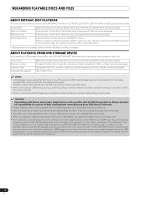 12
12 13
13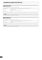 14
14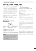 15
15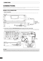 16
16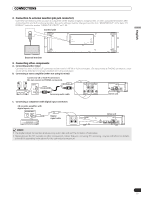 17
17 18
18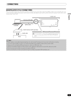 19
19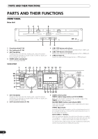 20
20 21
21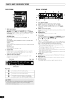 22
22

