Pioneer MEP-7000 Owner's Manual - Page 23
Rear Panel - software
 |
UPC - 012562879185
View all Pioneer MEP-7000 manuals
Add to My Manuals
Save this manual to your list of manuals |
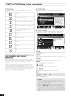
Page 23 highlights
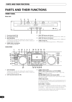
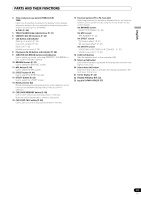
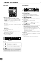
English PARTS AND THEIR FUNCTIONS REAR PANEL Drive Unit 5 1 23 4 6 7 AC IN PC USB1 DIGITAL OUT BA B AUDIO OUT L R A AUDIO OUT L R CONTROL CONTROL REMOTE CONTROL 1 AC inlet (AC IN) Use the supplied power cord to connect this inlet to a household AC outlet. 2 PC connector: USB port (type B) Use the supplied USB cable to connect this port to a computer. 3 USB1 port (type A) Use to connect a USB storage device or USB keyboard. 4 Digital output connectors (DIGITAL OUT A/B) RCA-type coaxial digital output connector for connecting a DJ mixer, AV amplifier, CD recorder or other component supporting digital input. The output supports all functions including DJ function, but only audio data not including subcodes is output. 5 Control jacks (CONTROL A/B) When the supplied control cord is used to connect this unit to a Pioneer DJ mixer, the DJ mixer can be used to control this unit so as to perform fader start play and back cue operations. Also, by connecting this jack to another DJ player's control jack, automated relay play can be performed.* * Relay play is disabled during DJ software track selection. 6 Audio output connectors (AUDIO OUT A/B) RCA-type analog audio output connectors. 7 Remote control connector (REMOTE CONTROL) Use the supplied dedicated remote control cable to connect to the control unit. Control Unit 1 PC 2 5V MONITOR OUT 3 REMOTE CONTROL 4 1 PC connector: USB port (type B) Use the accessory USB cable to connect this port to a computer. 2 5 V connector Use the accessory USB auxiliary power cable to connect to a computer. 3 Video output connector (MONITOR OUT) Use a video cable to connect to an external display. 4 Remote control connector (REMOTE CONTROL) Use the supplied dedicated remote control cable to connect to the drive unit. 23 En
-
 1
1 -
2
-
3
-
4
-
5
-
6
-
7
-
8
-
9
-
10
-
11
-
12
-
13
-
14
-
15
-
16
-
17
-
 18
18 -
 19
19 -
 20
20 -
 21
21 -
 22
22 -
 23
23 -
 24
24 -
 25
25 -
 26
26 -
 27
27 -
 28
28 -
29
-
30
-
31
-
32
-
33
-
34
-
35
-
36
-
37
-
38
-
39
-
40
-
41
-
42
-
43
-
44
-
45
-
46
-
47
-
48
-
49
-
50
-
51
-
52
-
53
-
54
-
55
-
56
-
57
-
58
-
59
-
60
-
61
-
62
-
63
-
64
-
65
-
66
-
67
-
68
-
69
-
70
-
71
-
72
 |
 |
