Pioneer PDP6100HD Owner's Manual - Page 12
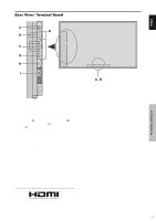
Rear View/ Terminal Board - speakers
 |
UPC - 012562773780
View all Pioneer PDP6100HD manuals
Add to My Manuals
Save this manual to your list of manuals |
Page 12 highlights
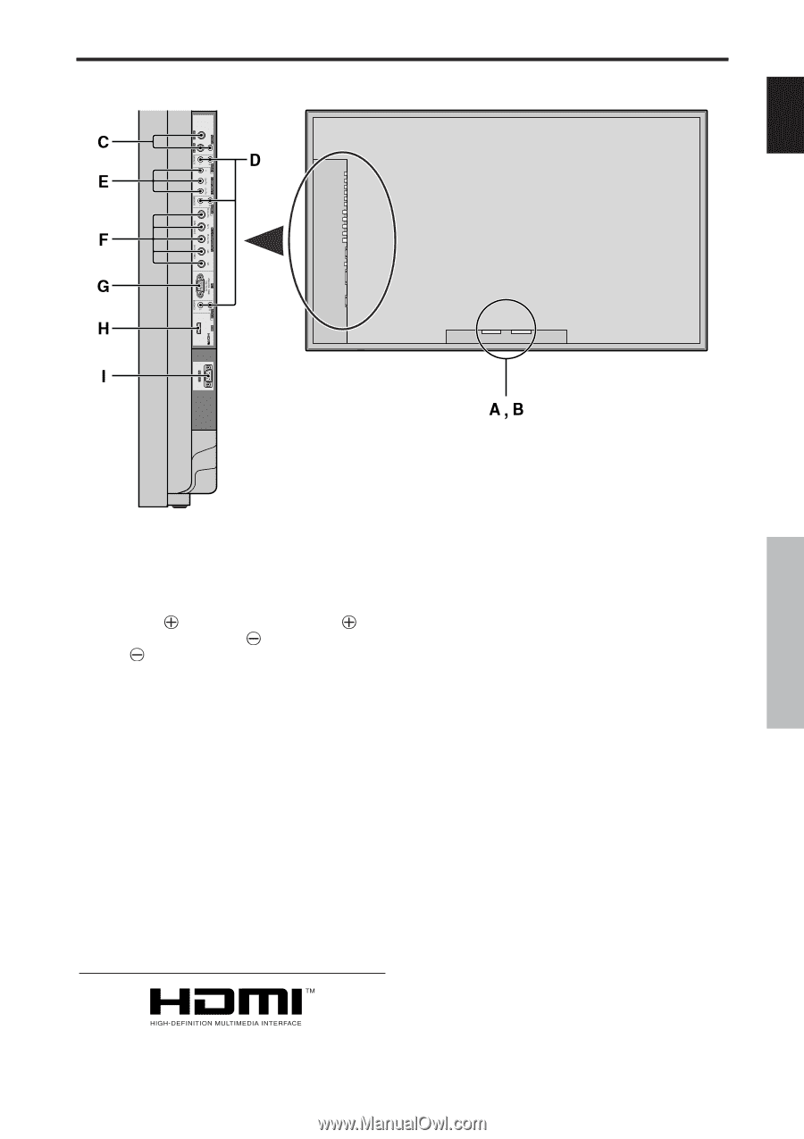
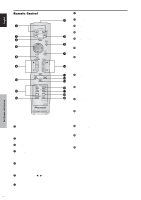
Rear View/ Terminal Board English Part Names and Function A AC IN Connect the included power cord here. B EXT SPEAKER L and R Connect speakers here. Maintain the correct polarity. Connect the (positive) speaker wire to the EXT SPEAKER terminal and the (negative) speaker wire to the EXT SPEAKER terminal on both LEFT and RIGHT channels. Please refer to your speaker's owner's manual. C VIDEO1, 2, 3 (BNC, RCA, S-Video) Connect VCR's, DVD's or Video Cameras, etc. here. D AUDIO1, AUDIO2, AUDIO3 These are audio input terminals. The input is selectable. Set which video image to allot them from the SOUND menu screen. E COMPONENT 1 Connect DVD's, High Definition or Laser Discs, etc. here. F PC2/ COMPONENT2 PC2: You can connect an analog RGB signal and the syncronization signal. COMPONENT2: You can connect DVDs, High Definition sources, Laser Discs, etc. here. This input can be set for use with an RGB or component source (see page 19). G PC1 (D-Sub) Connect an analog RGB signal from a computer, etc. here. H HDMI Connect a digital signal from a source with a HDMI output. See page 30 for the details of Supported Signals. I RS-232C Never connect any component to this connector without first consulting your Pioneer installation technician. This connector is used for plasma display setup adjustments. HDMI, the HDMI logo and High-Definition Multimedia Interface are trademarks or registered trademarks of HDMI Licensing LLC. 5 En
-
 1
1 -
2
-
3
-
4
-
5
-
6
-
 7
7 -
 8
8 -
 9
9 -
 10
10 -
 11
11 -
 12
12 -
 13
13 -
 14
14 -
 15
15 -
 16
16 -
 17
17 -
18
-
19
-
20
-
21
-
22
-
23
-
24
-
25
-
26
-
27
-
28
-
29
-
30
-
31
-
32
-
33
-
34
-
35
-
36
-
37
-
38
-
39
-
40
-
41
-
42
-
43
-
44
-
45
-
46
-
47
-
48
-
49
-
50
-
51
-
52
-
53
-
54
-
55
-
56
-
57
-
58
-
59
-
60
-
61
-
62
-
63
-
64
-
65
-
66
-
67
-
68
-
69
-
70
-
71
-
72
-
73
-
74
-
75
-
76
-
77
-
78
-
79
-
80
-
81
-
82
-
83
-
84
-
85
-
86
-
87
-
88
-
89
-
90
-
91
-
92
-
93
-
94
-
95
-
96
-
97
-
98
-
99
-
100
-
101
-
102
-
103
-
104
-
105
-
106
-
107
-
108
-
109
-
110
 |
 |