Ricoh C811DN Operating Instructions - Page 15
Exterior: Rear View - transfer unit installation
 |
UPC - 026649028182
View all Ricoh C811DN manuals
Add to My Manuals
Save this manual to your list of manuals |
Page 15 highlights
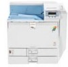
Exterior: Rear View Exterior: Rear View This section explains names and functions of the parts on the rear side of the printer. 1 ATU002S 1. Optional Interface Board Slots Optional interface boards can be inserted. Insert an optional Gigabit Ethernet board, IEEE 802.11b interface unit, Bluetooth interface unit or IEEE1284 interface board in the left slot. Insert a USB host board in the right slot. 2. Expansion Card Slots Insert a security, digital camera or encryption card. 3. Controller Board Slide this out to install options such as the SDRAM module or User Account Enhance Unit. 4. Ventilator Releases heat from internal components to prevent overheating. Do not place objects against or near these holes. Doing so results in printer malfunction. Replace the dustproof filter when the "Replacement Alert/Replace IntTrans Unit soon." message appears on the display. Replace it with the intermediate transfer unit together. 5. Power Connector Connect the power cable to the printer. Insert the other end into an electrical outlet. 6. Drying Heater Switch If the paper in the paper tray is moist due to high humidity, the print quality may decrease. The drying heater prevents moisture. If humidity is high, turn the switch on. 7. Ethernet Port Use a network interface cable to connect the printer to the network. 13
-
 1
1 -
2
-
3
-
4
-
5
-
6
-
7
-
8
-
9
-
 10
10 -
 11
11 -
 12
12 -
 13
13 -
 14
14 -
 15
15 -
 16
16 -
 17
17 -
 18
18 -
 19
19 -
 20
20 -
21
-
22
-
23
-
24
-
25
-
26
-
27
-
28
-
29
-
30
-
31
-
32
-
33
-
34
-
35
-
36
-
37
-
38
-
39
-
40
-
41
-
42
-
43
-
44
-
45
-
46
-
47
-
48
-
49
-
50
-
51
-
52
-
53
-
54
-
55
-
56
-
57
-
58
-
59
-
60
-
61
-
62
-
63
-
64
-
65
-
66
-
67
-
68
-
69
-
70
-
71
-
72
-
73
-
74
-
75
-
76
-
77
-
78
-
79
-
80
-
81
-
82
-
83
-
84
-
85
-
86
-
87
-
88
-
89
-
90
-
91
-
92
-
93
-
94
-
95
-
96
-
97
-
98
-
99
-
100
-
101
-
102
-
103
-
104
-
105
-
106
-
107
-
108
-
109
-
110
-
111
-
112
-
113
-
114
-
115
-
116
-
117
-
118
-
119
-
120
-
121
-
122
-
123
-
124
-
125
-
126
-
127
-
128
-
129
-
130
-
131
-
132
-
133
-
134
-
135
-
136
-
137
-
138
-
139
-
140
-
141
-
142
-
143
-
144
-
145
-
146
-
147
-
148
-
149
-
150
-
151
-
152
-
153
-
154
-
155
-
156
-
157
-
158
-
159
-
160
-
161
-
162
-
163
-
164
-
165
-
166
-
167
-
168
-
169
-
170
-
171
-
172
-
173
-
174
-
175
-
176
-
177
-
178
-
179
-
180
-
181
-
182
-
183
-
184
-
185
-
186
-
187
-
188
-
189
-
190
-
191
-
192
-
193
-
194
-
195
-
196
-
197
-
198
-
199
-
200
-
201
-
202
-
203
-
204
-
205
-
206
-
207
-
208
-
209
-
210
-
211
-
212
-
213
-
214
-
215
-
216
-
217
-
218
-
219
-
220
-
221
-
222
-
223
-
224
-
225
-
226
-
227
-
228
-
229
-
230
-
231
-
232
-
233
-
234
-
235
-
236
-
237
-
238
-
239
-
240
-
241
-
242
-
243
-
244
-
245
-
246
-
247
-
248
-
249
-
250
-
251
-
252
 |
 |
