Ricoh CL7200DT2 Setup Guide - Page 73
order of the numbers 1 to 4 next to the screw holes.
 |
UPC - 026649024139
View all Ricoh CL7200DT2 manuals
Add to My Manuals
Save this manual to your list of manuals |
Page 73 highlights
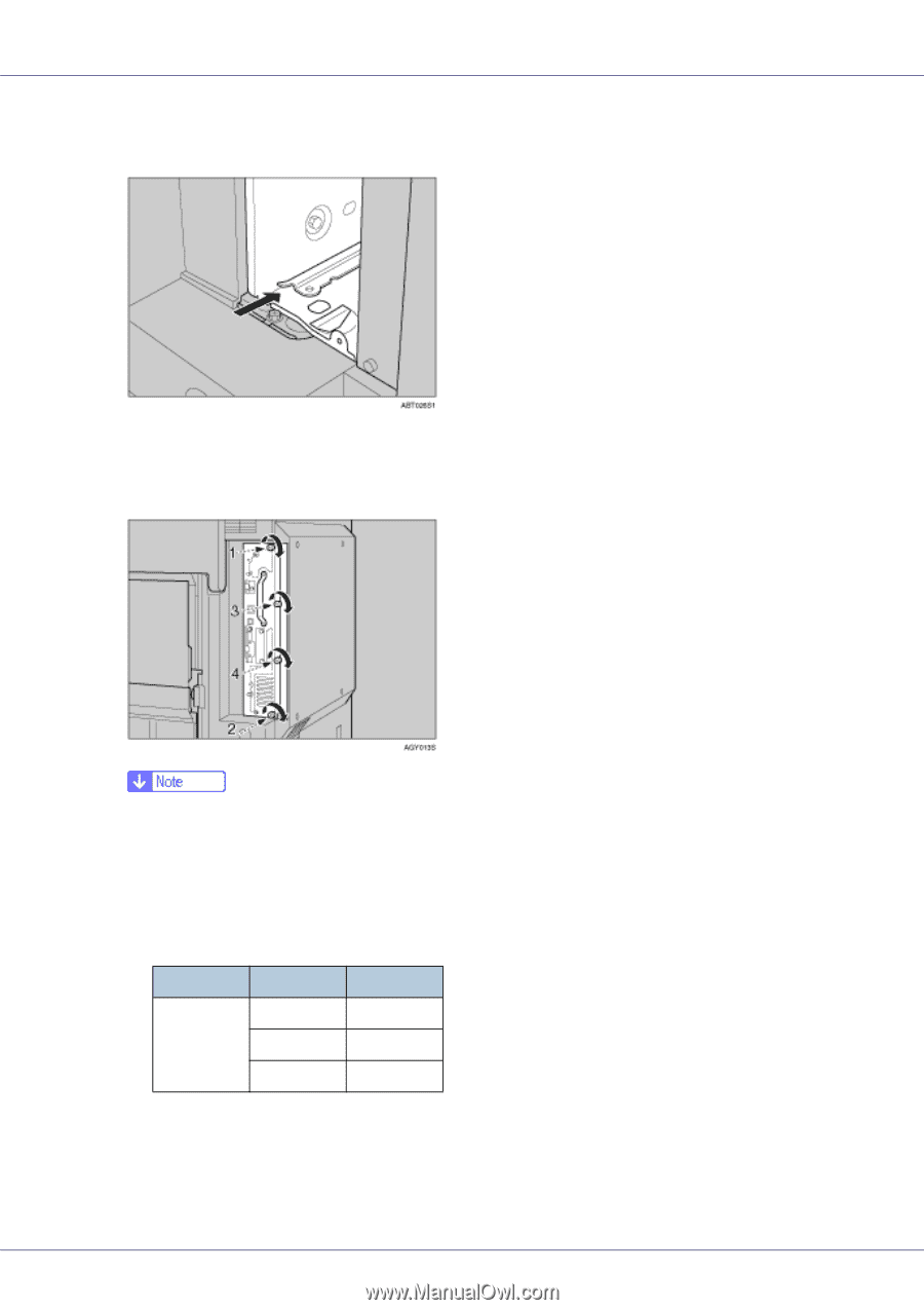
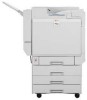
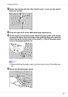
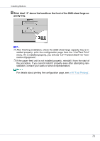
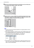
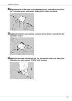
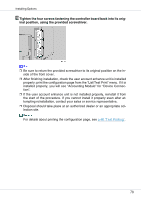
Installing Options I Align the controller board with the top and bottom rails, and then push it in using the part marked "PUSH" until it stops. J Tighten the four screws to fasten the controller board back into its orig- inal position using the provided screwdriver. Tighten the screws in the order of the numbers (1 to 4) next to the screw holes. ❒ Be sure to return the provided screwdriver to its original position on the inside of the front cover. ❒ After finishing installation, check the memory unit is installed properly: print the configuration page from the "List/Test Print" menu. If it is installed properly, you will see the memory capacity for "Total Memory". ❒ The table below shows total SDRAM module capacities. Standard Extended Total 64 MB 320 MB 256 MB 128 MB 384 MB 256 MB 512 MB ❒ If the memory unit is not installed properly, repeat the procedure from the start. If you cannot install it properly even after reinstallation, contact your sales or service representative. 73
-
 1
1 -
2
-
3
-
4
-
5
-
6
-
7
-
8
-
9
-
10
-
11
-
12
-
13
-
14
-
15
-
16
-
17
-
18
-
19
-
20
-
21
-
22
-
23
-
24
-
25
-
26
-
27
-
28
-
29
-
30
-
31
-
32
-
33
-
34
-
35
-
36
-
37
-
38
-
39
-
40
-
41
-
42
-
43
-
44
-
45
-
46
-
47
-
48
-
49
-
50
-
51
-
52
-
53
-
54
-
55
-
56
-
57
-
58
-
59
-
60
-
61
-
62
-
63
-
64
-
65
-
66
-
67
-
 68
68 -
 69
69 -
 70
70 -
 71
71 -
 72
72 -
 73
73 -
 74
74 -
 75
75 -
 76
76 -
 77
77 -
 78
78 -
79
-
80
-
81
-
82
-
83
-
84
-
85
-
86
-
87
-
88
-
89
-
90
-
91
-
92
-
93
-
94
-
95
-
96
-
97
-
98
-
99
-
100
-
101
-
102
-
103
-
104
-
105
-
106
-
107
-
108
-
109
-
110
-
111
-
112
-
113
-
114
-
115
-
116
-
117
-
118
-
119
-
120
-
121
-
122
-
123
-
124
-
125
-
126
-
127
-
128
-
129
-
130
-
131
-
132
-
133
-
134
-
135
-
136
-
137
-
138
-
139
-
140
 |
 |