Ridgid R4030 Operation Manual - Page 12
Assembly - tile saw manual
 |
View all Ridgid R4030 manuals
Add to My Manuals
Save this manual to your list of manuals |
Page 12 highlights
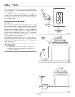
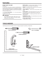
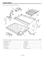
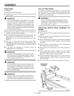
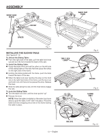
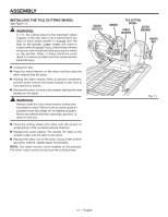
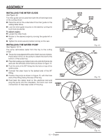
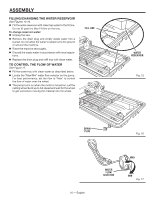
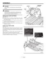
ASSEMBLY UNPACKING See Figure 5. This product requires assembly. Carefully lift the saw from the carton and place on a level work surface. WARNING: Do not use this product if any parts on the Loose Parts List are already assembled to your product when you unpack it. Parts on this list are not assembled to the product by the manufacturer and require customer installation. Use of a product that may have been improperly assembled could result in serious personal injury. Inspect the tool carefully to make sure no breakage or damage occurred during shipping. Do not discard the packing material until you have carefully inspected and satisfactorily operated the tool. NOTE: Many of the Loose Parts are stored in the water reservoir. The saw is factory set for accurate cutting. After assembling it, check for accuracy. If shipping has influenced the settings, refer to specific procedures explained in this manual. If any parts are damaged or missing, please call 1‑866‑539-1710 for assistance. WARNING: If any parts are damaged or missing do not operate this tool until the parts are replaced. Use of this product with damaged or missing parts could result in serious personal injury. WARNING: Do not attempt to modify this tool or create accessories not recommended for use with this tool. Any such alteration or modification is misuse and could result in a hazardous condition leading to possible serious personal injury. TILE CUTTING WHEEL For maximum performance and safety, it is recommended that you use the 7 in. cutting wheel provided with your saw. Additional cutting wheels of the same high quality are available at your local dealer. WARNING: Do not use cutting wheels rated less than the no load speed of this tool. Failure to heed this warning could result in personal injury. Do not use wheel with cracks, gaps, or teeth. INSTALLING MOTOR HEAD ASSEMBLY TO FRAME See Figures 6-8. Place spacers in the top holes of the frame as shown in figure 6. Align the holes in the motor head assembly with the holes on the water tray frame. From under the water tray frame, insert three socket head screws up through the frame, spacers, and motor head assembly. Secure screws in place using hex nuts. Finger tighten then lightly torque using wrenches. Place spacers in the side holes of the frame as shown in figure 7. Insert socket head screws through the motor head assembly, spacers, and into the side of the frame. Finger tighten then lightly torque using wrenches. Once all screws are lightly torqued, return to the first three screws and tighten. Tighten the two screws on the side of the frame last. Place the frame on the water tray as shown in figure 8. MOTOR HEAD ASSEMBLY WARNING: Do not connect to power supply until assembly is complete. Failure to comply could result in accidental starting and possible serious personal injury. HEX NUT SPACER 12 - English SOCKET HEAD SCREW Fig. 6
-
 1
1 -
2
-
3
-
4
-
5
-
6
-
 7
7 -
 8
8 -
 9
9 -
 10
10 -
 11
11 -
 12
12 -
 13
13 -
 14
14 -
 15
15 -
 16
16 -
 17
17 -
18
-
19
-
20
-
21
-
22
-
23
-
24
-
25
-
26
-
27
-
28
-
29
-
30
-
31
-
32
-
33
-
34
-
35
-
36
-
37
-
38
-
39
-
40
-
41
-
42
-
43
-
44
-
45
-
46
-
47
-
48
-
49
-
50
-
51
-
52
-
53
-
54
-
55
-
56
-
57
-
58
-
59
-
60
-
61
-
62
-
63
-
64
-
65
-
66
-
67
-
68
-
69
-
70
-
71
-
72
-
73
-
74
-
75
-
76
-
77
-
78
-
79
-
80
 |
 |