Ridgid R4030 Operation Manual - Page 23
Positive Stop Adjustments, To Adjust The Laser Guide
 |
View all Ridgid R4030 manuals
Add to My Manuals
Save this manual to your list of manuals |
Page 23 highlights
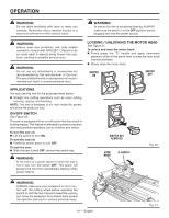
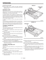
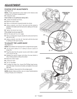
ADJUSTMENT POSITIVE STOP ADJUSTMENTS See Figure 30. NOTE: These adjustments were made at the factory and normally do not require readjustment. Unplug the saw. If the wheel is not perfectly vertical (0°): Loosen the bevel lock knob. Raise the motor head. Place a combination square beside the wheel. Using a wrench, turn the 0° hex bolt until the wheel is square to the table and the hex bolt is resting on the saw housing. Tighten the bevel lock knob. If the wheel is not an exact 45°: Set the saw arm to a 45° angle. Place a combination square beside the wheel and set the saw arm at 45°. Using a wrench, turn the 45° hex bolt until the hex bolt is resting on the saw housing. TO ADJUST THE LASER GUIDE See Figure 31. NOTE: Avoid direct eye exposure when using the laser guide. Use the work clamp or a C-clamp to secure a piece of scrap tile. Plug the saw into the power source and make a slight cut to score the tile. Release the switch trigger and allow the saw blade to stop rotating before raising the wheel. Raise the motor head. Unplug the saw. Turn on the laser. To adjust the laser line, loosen the Phillips head screw, adjust the laser module as needed, and tighten the screw securely. Once aligned, close and lock the wheel guard. NOTE: Always make practice cuts on scrap material before cutting through your workpiece. 45° BEVEL LOCK KNOB 0° SCREW 0 COMBINATION SQUARE 45 Fig. 30 23 - English Fig. 31
-
 1
1 -
2
-
3
-
4
-
5
-
6
-
7
-
8
-
9
-
10
-
11
-
12
-
13
-
14
-
15
-
16
-
17
-
 18
18 -
 19
19 -
 20
20 -
 21
21 -
 22
22 -
 23
23 -
 24
24 -
 25
25 -
 26
26 -
 27
27 -
 28
28 -
29
-
30
-
31
-
32
-
33
-
34
-
35
-
36
-
37
-
38
-
39
-
40
-
41
-
42
-
43
-
44
-
45
-
46
-
47
-
48
-
49
-
50
-
51
-
52
-
53
-
54
-
55
-
56
-
57
-
58
-
59
-
60
-
61
-
62
-
63
-
64
-
65
-
66
-
67
-
68
-
69
-
70
-
71
-
72
-
73
-
74
-
75
-
76
-
77
-
78
-
79
-
80
 |
 |
