Ridgid R4030 Operation Manual - Page 22
Adjustment
 |
View all Ridgid R4030 manuals
Add to My Manuals
Save this manual to your list of manuals |
Page 22 highlights
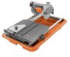
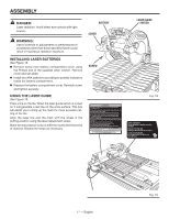
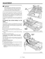
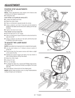
ADJUSTMENT WARNING: Before performing any adjustment, make sure the tool is unplugged from the power supply and the switch is in the OFF position. Failure to heed this warning could result in serious personal injury. The saw has been adjusted at the factory for making very accurate cuts. However, some of the components might have been jarred out of alignment during shipping. Also, over a period of time, readjustment will probably become necessary due to normal wear. Do not start any adjustments until you have checked with a square and made test cuts to be sure adjustments are needed. TO SQUARE THE CUTTING WHEEL TO THE TABLE See Figure 28. Do not loosen any screws for this adjustment until you have checked with a square and made test cuts to be sure adjustments are necessary. Once the screws are loosened, these items must be reset. Unplug the saw. Using a hex key, loosen cap bolts on the left rail. Place a framing square against the fence and the flat part of the wheel. Move the rail until the fence is square with the cutting wheel. Tighten the cap bolts securely. TO ADJUST THE LOWER TABLE ROLLERS See Figure 29. If the table doesn't slide smoothly, seems too loose on the rails, moves side to side, or is visibly off track adjustments may be required. To adjust if the table is loose: Loosen the cam bolt nut. Insert hex key through the hole in the left side of the table and adjust bolt as needed. Once the rollers are touching the rail, tighten the cam bolt nut securely. Repeat for each roller as required. NOTE: Check that rollers are sliding properly after each adjustment. CAP BOLTS FRAMING SQUARE CAM BOLT NUT 22 - English Fig. 28 Fig. 29
-
 1
1 -
2
-
3
-
4
-
5
-
6
-
7
-
8
-
9
-
10
-
11
-
12
-
13
-
14
-
15
-
16
-
 17
17 -
 18
18 -
 19
19 -
 20
20 -
 21
21 -
 22
22 -
 23
23 -
 24
24 -
 25
25 -
 26
26 -
 27
27 -
28
-
29
-
30
-
31
-
32
-
33
-
34
-
35
-
36
-
37
-
38
-
39
-
40
-
41
-
42
-
43
-
44
-
45
-
46
-
47
-
48
-
49
-
50
-
51
-
52
-
53
-
54
-
55
-
56
-
57
-
58
-
59
-
60
-
61
-
62
-
63
-
64
-
65
-
66
-
67
-
68
-
69
-
70
-
71
-
72
-
73
-
74
-
75
-
76
-
77
-
78
-
79
-
80
 |
 |