Ridgid R4030 Operation Manual - Page 13
Installing The Sliding Table
 |
View all Ridgid R4030 manuals
Add to My Manuals
Save this manual to your list of manuals |
Page 13 highlights
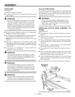
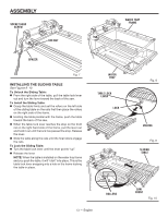
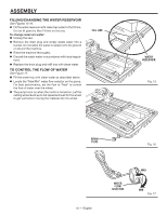
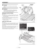
ASSEMBLY SOCKET HEAD SCREW HEX NUT WATER TRAY FRAME SPACER Fig. 7 INSTALLING THE SLIDING TABLE See Figures 9 -10. To Unlock the Sliding Table: From the right side of the table, pull the table lock lever out and turn the lever toward the back of the saw. To Install the Sliding Table: Grasp the table firmly and set the rollers on the left side of the sliding table on the rails first then place the rollers on the right side of the frame. Holding the table parallel with the frame, push the table toward the back of the saw. When the table lock lever reaches the stop on the front rail on the right hand side of the frame, pull the lever out and hold it out until the lock has passed the stop. Release the lever. Slide the table along the rails until the final rollers engage the rails. To Lock the Sliding Table: Turn the table lock lever until the lever points "up". Release the lever. NOTE: When the table is installed on the water tray frame and you push the table, it will "click" into place. This is the table lock lever snapping into a hole in the frame locking the table in place. WATER TRAY TABLE LOCK LEVER LOCK Fig. 8 UNLOCK Fig. 9 SLIDING TABLE ROLLERS 13 - English SAW FRONT Fig. 10
-
 1
1 -
2
-
3
-
4
-
5
-
6
-
7
-
 8
8 -
 9
9 -
 10
10 -
 11
11 -
 12
12 -
 13
13 -
 14
14 -
 15
15 -
 16
16 -
 17
17 -
 18
18 -
19
-
20
-
21
-
22
-
23
-
24
-
25
-
26
-
27
-
28
-
29
-
30
-
31
-
32
-
33
-
34
-
35
-
36
-
37
-
38
-
39
-
40
-
41
-
42
-
43
-
44
-
45
-
46
-
47
-
48
-
49
-
50
-
51
-
52
-
53
-
54
-
55
-
56
-
57
-
58
-
59
-
60
-
61
-
62
-
63
-
64
-
65
-
66
-
67
-
68
-
69
-
70
-
71
-
72
-
73
-
74
-
75
-
76
-
77
-
78
-
79
-
80
 |
 |
